"but it's equivalent to a 2V anode voltage"
Ummh, yeah. The substrate diode ruins the voltage range. Maybe there are some RF Mosfets or something that don't have the substrate diode? I read where the analog mux chips just bias the substrate to some neg. voltage, below the signal operating range, to keep it from conducting.
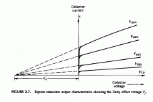
There are some other options too. The Early effect in bipolars and channel modulation in Mosfets (smaller effect) puts some slope on the "pentode" curves.
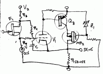
One can use them as triode curves by putting a Mosfet cascode on top, load it's drain with a CCS, and then the drain/CCS point controls a source follower (with some voltage drop) back to the cascode gate. The source follower will then have Mu times gain versus the input (well, sorta for the bipolar case).
Don
Attachments
6229387
http://www.google.com/patents?id=1IUGAAAAEBAJ&dq=6229387
Regarding PNP current mirror boost above the plate.
Not exactly the same as Tubelab's which relies on constant beta.
And substantially different than NPN mirror under the cathode....
But worth the read anyways...
http://www.google.com/patents?id=1IUGAAAAEBAJ&dq=6229387
Regarding PNP current mirror boost above the plate.
Not exactly the same as Tubelab's which relies on constant beta.
And substantially different than NPN mirror under the cathode....
But worth the read anyways...
Re: 6229387
Mine is better.

kenpeter said:http://www.google.com/patents?id=1IUGAAAAEBAJ&dq=6229387
Regarding PNP current mirror boost above the plate.
Not exactly the same as Tubelab's which relies on constant beta.
And substantially different than NPN mirror under the cathode....
But worth the read anyways...
Mine is better.

Patent "6229387"
This is a sorta an odd patent if you ask me. The use of the ratio'd current mirror is clever for increasing current by a relatively modest ratio (maybe up to 10). There is also another patent on using the Sziklai pair with a tube which allows higher current gain ratios easily. (uses a PNP, an obvious re-patent that clearly should not have been granted however)
But the current mirror scheme puts resistance in series with the tube, which is not so good. Then they go on to make a fancier version using current and voltage amps on the output side of the transformer so as to scale voltage and current for the tube. But all the time they show a pentode, which doesn't care anyway. I think this all just goes to show that anything goes for guitar amplifiers. But their basic idea of scaling a small amplifier up to a big one is on the right track.
The simple Darlington circuit allows one to multiply current and preserve plate voltage, and is so much simpler. (I hope someone has not gone and re-patented the Darlington now)
The Un-transformer in post 32 (attached again) or the screen feedback loop in post 28 are very simple ways to out-perform this patent.
Don
Attachments
Don;
do you think that a simple Darlington arrangement of a tube and transistor (FET, BJT - don't matter) may be used for free, like an air?
do you think that a simple Darlington arrangement of a tube and transistor (FET, BJT - don't matter) may be used for free, like an air?
"do you think that a simple Darlington arrangement of a tube and transistor (FET, BJT - don't matter) may be used for free, like an air?"
Not completely, but a few attentions to details will go a long way:
A low capacitance Mosfet of Jfet/Mosfet combo should do pretty good for making a tube/SS Darlington as long as sufficient voltage is kept across the drain - source to minimize the capacitance and it's variation. (and if the tube plate is connected to the drains, this shouldn't be a problem at all) The Mosfet does not have a near constant Beta like the bipolar, so some source degeneration could be helpful. Operating the Mosfet at higher currents too, brings its gain closer to linear rather than square law.
For the bipolar, I would suggest using a cascode Mosfet above it to minimize collector-base junction voltage variation. The base-emitter junction could be buffered by a Mosfet source follower to minimize variable capacitance there. Could use a thermionic diode in series with the base to lower the gm and make it look like a tube as well. The bipolar should be a near constant Beta device, or at least biased up so as to be operating in the flat Beta region.
In all cases, the tube plate is connected to the drain or collector output terminal so as to provide accurate plate voltage feedback.
Don
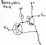
There is also the Baxandall/Hawksford (I think its called that, I would apply it here to the bipolar Darlington) cascode, where the top device base or gate is referenced back to an emitter degeneration resistor for the bottom device (100 Ohm typ.). That way top coll. - base capacitance and top base currents get subtracted out at the degen. resistor. (Gary Pimm made good use of this for his CCS designs to get very low cap. and very high Zout. )
That way a bipolar cascode could be used on top to minimize the voltage variation across the bottom bipolar coll. to base junction.
Also helps to get as much DC voltage across this junction as possible to minimize capacitance too.
Don
There is also the Baxandall pair, instead of the Darlington. (attached) It has some advantages regarding capacitances.
Attachments
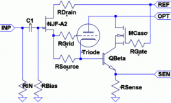
A2 vs RSense
I think I got a prob here. And this drawing is not a solution.
Want to keep A2 current out of the RSense (for Anti-Triode
not shown in this drawing). But this disguise for transition
to A2 drive current only makes it worse.
I would work on it some more before posting, but I am done
for tonight and wanted to show something for my efforts.
Even if its completely half baked...
RSource prollyshoulda gone to ground instead of QBeta...
Attachments
Hi Ken,
I think I see what you are trying to do, compensate Qbeta base current for the G1 current in A2. Rsource does seem to be having two effects, changing the tube current down and changing the Qbeta current up. The net result probably not what you want though.
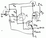
I think I would move Rsource to ground (maybe even replace with a CCS). Then an R-C from Rdrain/NJF to the cathode. This will reduce Qbeta base current with A2 current draw so as to compensate for the g2 current. It will also decrease the bias on the tube, causing it's current to increase. But the grid stopper causes grid bias to increase in A2 (causing tube current to decrease), so maybe one effect can be made to balance out the other effect on bias (becoming a nice fix for a common problem with A2 op.).
Just for fun, I scribbled up the same A2 mods on the Sziklai version, works out the same way I think. (Oops, left off a gate stopper on the Mosfet)
Don
Attachments
Hmm. I have driven my test amp into A2 and don't recall any strange behavior. I don't really have a good driver for A2 though; the 2nd generation amp I'm building now will have a circuit like the tubelab powerdrive and I'll be able to investigate the A2 effects further.
The particular currents and component values may be important in a grid current compensation scheme. Maybe the grid current can be subtracted out of the mirror current at the opamp input terminals.
NB some of the grid current will be due to the miller capacitance and goes into the anode circuit. Subtracting this from the cathode mirror current may introduce an error on fast-slewing signals like the 10KHz square wave test. I get up to 1-2 mA at max dv/dt in some cases.
Ken -- I would like to ask you a question off-forum. Would you email me through the forum email? (if you don't mind)
Cheers
Michael
re: Michael
"NB some of the grid current will be due to the miller capacitance and goes into the anode circuit. Subtracting this from the cathode mirror current may introduce an error on fast-slewing signals like the 10KHz square wave test. I get up to 1-2 mA at max dv/dt in some cases."
Hmmm, good point. I think maybe a small cap across the Fet drain resistor can compensate for this in the modified Ken's diagram. Will decrease the A2 current compensation with fast slew rate.
But then again, the A2 current onset is rapid too, so this fix would slow down the compensation for that. Need a more sophisticated comp. I guess. Need something like neutralization for the plate-grid capacitance, but I don't see any good inverted signal available here to do that. In the Sziklai case, maybe can get it from the Qb collector.
Don
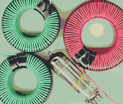
I finished up the latest toroid xfmrs for the Switchless Circlotron converter version. Using the same cores as before. All HV windings are single layer for low distributed capacitance. TFE #22 wire.
The two B+ xfmrs have 66 turns on the medium core, 36 mH, HF magnetization current is 2% of signal current, capable of up to 1160 V pk at 1200 Gauss at 125 KHz, self resonant at 167 KHz
The large core is for the Circlotron plate winding, has 88 turns, 68 mH, HF magnetization current is 1% of signal current, capable of up to 2700 V pk at 1200 Gauss at 125 KHz, self resonant at 107 KHz
I may go for a few less turns on the plate core next time to bring the self resonant freq. up to the 125 KHz range. I think having the self resonance (dist. cap. and primary L) at the switching frequency will mostly null out the magnetization current.
Now to get the controller wired up.
Don
Attachments
Hiding A2 grid current
By the time A2 starts, not all that significant by comaprison
to plate-cathode current. Am I worried about nothing?
My concern it might mess with DC offset in the Anti-Triode.
I might be multiplying this A2 error current many times....
Or I could be on about a problem that doesn't even exist,
I havn't had time to stew on the question and dream of
what happens when electrons start moving.
Clearly the PNP solution at the plate has no such problem,
its just that Korg patent. And I hate plagiarizing from other
peoples work when circumventing is so much more fun.
I wonder if the low voltage output > plate step-up could be
replaced by a simple diode (or synchronous) ladder and no
transformer at all? I don't wanna copy off Berning either, if
I can cook up a plausible way to avoid it.
I keep thinking bilateral FET opto-isolators might be helpful
somehow. Especially if there were such thing as a matched
pair of them... How to drive a synchronus ladder?
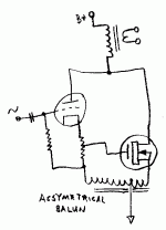
And baluns... True baluns (Transmission line transformers.)
Not really a magnetic transformer as such, merely a balanced
transmission line with a common mode choke... A few of them
tied together parallel on one end, and series on the other...
That might work, but Trasmission lines are limited to around
75~100ohms impedance apiece, or the spacing between the
bifilar or coaxial pair becomes absurd...
Is a balun still a balun if sum impedance of the transmission
line(s) do not (in parallel or series) match either end? Does
mismatch matter at all when the lines are likely far shorter
than a quarter wave at the switching frequency? Do I care
only about the common mode blocking impedance?
Hi Ken,
"By the time A2 starts, not all that significant by comaprison
to plate-cathode current. Am I worried about nothing?"
The grid current is a rapidly rising curve as you get further positive, depends on how far you drive it. Have to see the data for a particular tube.
"Korg patent"
I think this patent is a work-around of the other patent on the tube-Sziklai myself. The multiplying current mirror thing is kinda just unnecessary overkill for guitar amps.
"synchronous) ladder"
I guess you mean a cap. voltage multiplier here? The problem with them is they don't like sudden changes in voltage across the caps, like in switching. That's why I used a resonant scheme to charge the caps for the SCIC. Another way would be to use a flyback inductor to act as a current source to charge the caps more smoothly. Should work well. In fact, PWM could be used there too. I'll draw something up tomorrow.
"Transmission line transformers"
I've looked at these. The series connect on one end and parallel connect on the other scheme (with common mode chokes over the lines) has a lot of redundant line sections if you look at it closely. (you can chop out a triangular section of lines) Think: how much common mode inductor is actually needed for each section (determines magnetization current in the end). It varies up the stack with the actual CM voltage swing. When you strip out the extra un-needed stuff, you end up with something similar, but not quite the same as an auto-xfmr. Like a bunch of overlapped auto-xfmrs. Still ends up requiring twice as many primary turns as an ordinary OT. Not so attractive.
(you don't have to worry about wavelengths or reflection coefficients at audio, but you do have to worry about the magnetization current, or equivalently, the primary inductance from the CM chokes. The 20 HZ bandwidth kills it.)
I suppose one could try to do a switchmode version of the transmission like xfmr. Use two of them and switch back and forth at HF as to which one is connected to the tubes. That way we avoid the 20 Hz problem. But I think this will likely end up as something similar to the Berning scheme, just be using an odd HF xfmr with twice as many turns as usual. I'll look at it tomorrow, you never know....
Don
I am not getting why you assume twice as many primary turns.
Except that both windings are bifilar primaries. And there is no
secondary whatsoever...
If we had two transmission line transformers, in parallel on the
low side, in series on the high side. We double the AC voltage
(or quadruple the impedance).
Nevermind that it may look a dead short or "useless" turns at
DC frequency, we are assuming reasonable impedance at the
switching frequency. And it ceases to tranfer energy by balun
if we take out the "useless" shorted windings, they are fully
functional and necessary part of the transmission delay lines.
Wacky stuff to warp one's mind....
Anyways, with two in series on one end, the middle terminal
might be ground (or not) and the common mode of each balun
at that end is 1/2 the switching signal. The common mode at
the parallel end is non-existant. Thats about 1/4 the switching
signal the core impedance must block, A lot LESS turns than a
normal or auto transformer that must have 4 times as much
impedance to block the full switching voltage.
But there are 2 bifilar turns (compared to one for autoXform)
and 2 baluns would quickly bring the total turns back up to
the same. More baluns, more turns... But not all on one core.
Most baluns are wound a single layer bifilar wrap on a toroid,
DIY construction is simple enough. And switched high enough,
CM impedance is not that great of a challenge. But the bulk
of having many physically separate cores might be at issue
if we need a large step-up.
We only need step up enough that the sum of diode drops
in the bridge or ladder that follow are not a significant loss.
I am not convinced that a balun array is any better than
Transonar, except that I don't have the means to build a
Transonar other than 1:1. And at that ratio I'd have to
parallel-series several the same way as baluns anyhow...
Hi Ken,
On the number of turns, this obviously depends on the implementation used, so it's difficult to compare apples with apples without tying things down considerably. (like equal total amount of magnetic material)
I was considering everthing wound on the same magnetic core, which "usually" is optimum for getting the best inductance per length of wire due to the mutual inductance effect. (ie. L varies as N squared, where for series chokes L varies as L linear)
I say "usually", because it theoretically is possible to get the same inductance with the same amount of material with a linear choke scheme if the magnetic material is wrapped right on the wire. (for an interesting related thread: http://www.diyaudio.com/forums/showthread.php?postid=626852#post626852 ) But practically oriented, this mechanically exposes the magnetic material to wire bending and wrapping curvature which is N.G.
But turns issues aside, the real attraction of the trans. line xfmr would be if the common mode could be switched at HF to avoid the 20 HZ inductance requirement. But at the same time the differential mode audio did not have to be switched, so no demod. would be required at the low Z end. Unfortunately, I don't think this is possible, due to the autotransformer equivalence at low frequency. (ie, CM and diff. mode are related here)
For just replacing a conventional HF xfmr. for any of the switched converter schemes, that should work fine. But I don't see any advantage particularly over an ordinary ferrite xfmr. unless you are contemplating mult-MHz operation. The capacitance multiplier scheme does gain advantage with higher frequency in decreasing the capacitor size. Conceivably one could make a chip converter at VHF.
Don
multiple cores
FYI, baluns are usually not wound all on the same core.
Or if more than one is wound through the same chunk
of core material, never on the same magnetic path.
Don't remember now the exact reason why... Or if it
only matters (separate cores) in certain circumstances.
If each transmission line blocks an equal share of the
same common mode signal, I don't see why it would
be a problem?
That would be a question for W2FMI.
Roswell Circlotron
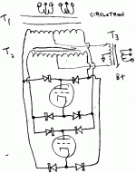
After reading the latest TubeCad blog, where J.B. mentions that some think the Circlotron came from Roswell, I had some dreams about Roswell and the aliens were insistent on reconfiguring my Switchless Switchmode Circlotron! (maybe it had something to do with listening to that "1st Sound recording" Backwards! Hehe) So here is the Roswell Circlotron version (attached). 😀
The general rule uncovered here is that the B+ xfmr and the plate xfmr in any of the configuratins can be swapped. Giving 6 front-end versions total. So I'll have some more schemes to post. (The Roswell Circlo. is the swap of the U.C. Switched Circlo. in post 115.)
Don
Attachments
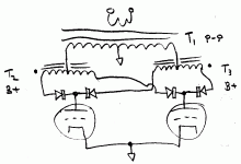
So, here is the backwards swap of the Switchless Switchmode Conv. front-end. (from post 83) Call it the Inverted Switchless Switchmode converter front-end, or ISSC front-end. T2 and T3 can be combined on one core.
I'm not going to bother posting the swapped version of the variable % CFB version in post 90, too complex to draw again. Just call T1 the B+ xfmr, and T2 the plate xfmr and you have it.
With this increased selection of front-end configurations, there are some useful optimizations for xfmr winding to reduce distributed capacitance. For example, the inverted SSC has only one P-P plate winding (versus two in the SSC), and this generally has twice the turns of the B+ windings, so this is a good choice here.
The Roswell Circ. version only uses one B+ xfmr and two plate windings (or xfmrs) (T1 and T2 can be combined on the same core). But the plate windings here are only half the usual P-P xfmr plate winding turns (like all Circlotrons), so this is a good choice here.
Don
Attachments
- Status
- Not open for further replies.
- Home
- Amplifiers
- Tubes / Valves
- Another kind of hybrid
