I read with excitement the 555 story; lot to re-learn and learn. Chris: the plot to the movie "...of the blown output stage" is something which all users of audio equipment should read before they destroy the equipment. My own amp suffered the same fate; I learned that they just turned the thing "ON". It was Canadian with oversized transformers, but not protection of any kind. Bryston would be better amp, at least the schematics are available and it always helps.
Chris, I'm in Barrie for now, so maybe one day I will go to Georgetown.
Chris, I'm in Barrie for now, so maybe one day I will go to Georgetown.
Wow, Chris, that was a cool blow-by-blow of a circuit failure. I hope James Cameron does the movie version! 🙂 And I hope that's not the fate that awaits this amp... Yes, best not to think about that.
Back on track. Finally able to do the PS testing. Here's how I set up the test:
1. Disconnected the output section by pulling the fuses
2. Connected my scope and a 150 watt bulb (as a load) across the + and - terminals of each power supply cap. The scope was set to AC coupling and ranged to .1v/div and 2ms/div. The probe was set to 10x and the 10x gain on the scope was on.
3. Ran up the power to full voltage.
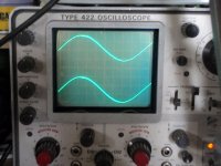
The result was the attached traces. Also, with the DVM each supply measured about -/+76vdc under load and 84vdc without a load. The amp pulled about .5 amp under the load, btw.
I think I'm seeing something similar to what G2 described in #152, except this is a 125hz, 400mv p-p ripple. Am I reading the trace wrong or is my ripple nearly twice his?
In any case, I think I can safely conclude my PS is okay. Do you guys agree?
What's my next move?
I think your power supply is a little better than mine and your scope could maybe use a calibration. Please do NOT attempt to calibrate your own scope at this point in your experience. At some point you may be ready but it's much better to stay out for now. Your ripple frequency is exactly 120 Hz in North America or else the power grid wouldn't work. You _might_ have an issue with the vertical gain cal as well but unless you have access to accurate reference signals... Have you tried the CAL test point on the front of the scope ? (or does the 422 not have that item?). If the probes are not the _real_ Tek article that _could_ maybe explain the discrepancy. As a test, you could use your variable DC supply and voltmeter to set a fixed value and set the scope to DC coupling to get an idea if the scope agrees with the meter. It should - and if it doesn;t you could get a 'correction' factor until the cal gets corrected (it might not need anything).
In my rush last week I didn't even bother measuring the DC voltages loaded or unloaded, just the ripple amplitude. I use my scope in video now and then and I'm pretty certain it's 'real close'.
G²
I think your power supply is a little better than mine and your scope could maybe use a calibration. Please do NOT attempt to calibrate your own scope at this point in your experience. At some point you may be ready but it's much better to stay out for now. Your ripple frequency is exactly 120 Hz in North America or else the power grid wouldn't work. You _might_ have an issue with the vertical gain cal as well but unless you have access to accurate reference signals... Have you tried the CAL test point on the front of the scope ? (or does the 422 not have that item?). If the probes are not the _real_ Tek article that _could_ maybe explain the discrepancy. As a test, you could use your variable DC supply and voltmeter to set a fixed value and set the scope to DC coupling to get an idea if the scope agrees with the meter. It should - and if it doesn;t you could get a 'correction' factor until the cal gets corrected (it might not need anything).
Hey G2,
I'm pretty confident my scope is calibrated because:
1. They guy I bought it from professionally refurbed and calibrated it. Though an ebay seller, he seems reputable and honest. (My scope's listing is still up). Granted this is subjective data!
2. It does have a CAL test point, and it reads dead spot-on with a 2v p-p square wave.
3. I compared the scope and DVM using my power supply as a DC source, as you suggested, and they agree precisely.
My probes are just chinese cheapies, but they seem to be working.
Those traces were obtained with the X10 GAIN AC engaged. With the probe set to 10x, that means I can just read the trace straight, no need to multiply or divide, right?
And don't worry, I would never think about mucking about with the scope's calibration. I know just enough to know how much I don't know. Some boxes are best left unopened. Arguably, this amp was one such box, but we'll see...
Okay, answering my own question, I think the next thing I need to do is establish that the good (R) channel is still working correctly. Then I will be able to use it as a baseline for checking values on the bad channel.
What's the best, safest way to do that?
To recap, I have the following test gear:
Heathkit IT-18 Transistor Checker
B+K 2707A DVM
Elenco XP-720 Power Supply
Velleman K7000 Signal Tracer/Injector
Velleman K8065 Audio signal generator
Tektronix 422 oscilloscope
Variac
What's the best, safest way to do that?
To recap, I have the following test gear:
Heathkit IT-18 Transistor Checker
B+K 2707A DVM
Elenco XP-720 Power Supply
Velleman K7000 Signal Tracer/Injector
Velleman K8065 Audio signal generator
Tektronix 422 oscilloscope
Variac
Hey G2,
I'm pretty confident my scope is calibrated because:
1. They guy I bought it from professionally refurbed and calibrated it. Though an ebay seller, he seems reputable and honest. (My scope's listing is still up). Granted this is subjective data!
2. It does have a CAL test point, and it reads dead spot-on with a 2v p-p square wave.
3. I compared the scope and DVM using my power supply as a DC source, as you suggested, and they agree precisely.
My probes are just chinese cheapies, but they seem to be working.
Those traces were obtained with the X10 GAIN AC engaged. With the probe set to 10x, that means I can just read the trace straight, no need to multiply or divide, right?
And don't worry, I would never think about mucking about with the scope's calibration. I know just enough to know how much I don't know. Some boxes are best left unopened. Arguably, this amp was one such box, but we'll see...
I was only curious because your ripple is nearly twice what mine is and while your capacitors are a little better than mine, neither is bad. The only way for the ripple to get larger is to either have less capacitance or a bigger load than I used but I think we both used a 150 Watt bulb. Electrolytic capacitor tolerances are very broad but all 4 of yours are very similar as well as all 4 of mine. They're just different.
Sounds like the scope cal is fine and no 'correction' is needed and you're using it correctly. The genuine Tek scope has an extra pin on the probe so when you attach it, the gain factor is taken care of for you (it just lights a different lamp). Just one less thing to have to remember but as a suggestion, keep the scope probe on X10 all the time and you won't make many mistakes. X1 mode is very rarely used (at least by me).
I think you're good to go to the next level and compare a good channel to the bad one. Personally I'd have the scope looking at the ouput of the amp while ramping up the supply but then again I use scopes all the time - more than my co-workers.
G²
I think you're good to go to the next level and compare a good channel to the bad one. Personally I'd have the scope looking at the ouput of the amp while ramping up the supply but then again I use scopes all the time - more than my co-workers.
Okay, I connected the scope to the good channel speaker outputs and ramped up the supply to full voltage. There was no load or input connected to the amp (but yes, I did remember to put the rail fuses back in).
I did not observe anything other than essentially a straight trace, even with the scope set down to.1v/div. I tried both AC and DC coupling, straight trace. I did measure -37mvdc at the speaker outs, and that voltage was visible on the scope.
There were no pops, crackles or snaps, no magic smoke was released nor did anything appear to heat up. In my assessment, so far so good.
I guess the next step would be to send a fixed audio signal (1khz?) through the good channel and compare the wave form going in to the waveform coming out, right?
How should I set up the load, etc. on the amp?
What you observed is exactly what it should be.
What I would do at this point is run the audio generator in at a low level, say 1 Watt (8 V p-p) into no load (just the scope) and then with an 8 ohm load. You should detect no difference between load / no load. Some (most?) will say you shouldn't connect the load while running but how is that different from switching speakers on/off in a receiver? The input level should be 347mV p-p for 8 volts out as the gain of the amp is 23. The output level should just rise nicely as you raise the input. What is happening on the bad channel? Offsets? waveform distortions? Any oscillations at any level? There should not be any. If your load resistors are big enough you might eventually 'crank it up' but don't overload your resistors. Heat is what destroys them and actively cooling them with a fan will allow somewhat more power. Personally I would run 2 volts P-P into the load with a 30-50KHz sine signal looking for crossover notches indicating low bias.
G²
What I would do at this point is run the audio generator in at a low level, say 1 Watt (8 V p-p) into no load (just the scope) and then with an 8 ohm load. <snip> The input level should be 347mV p-p for 8 volts out as the gain of the amp is 23.
I'm a little confused by this. Should I run the audio generator at 8v p-p or 347mv p-p? I'm sure I'm missing something.
In any case, at the moment the generator I have is this little doohickey. From what I think you're saying, it won't do the job.
Hi Fred,
Your capacitors are in excellent shape. No pips at all on the leading edge of the waveform. I'd be pretty happy right now if I were you.
The next task would be to run the amp up to normal operating voltage, slowly. Keep an eye on the current draw and your senses looking for smoke or snaps. Once you have safely got to normal running voltage, check DC offsets and bias currents. Take note of the bias and check it again later. It will rise over time, so expect this. Then run a low amplitude tone through a speaker. If you have dummy loads, connect them and run the amplifier at around 8 watts (8 vac across an 8 ohm resistor). Allow the amp to warm up for about 1/2 hour. Check it again for DC offsets and bias currents. Under load, you may see the results of an open emitter resistor in case you missed one.
Nice 'scope, it will do all you need, and it will have nifty features, When you take pictures of a trace, lower the beam intensity some more. The detail on the trace will be better. Otherwise, good work!
-Chris
Thanks guys for the input.
Still taking baby steps here... Still just working on testing the good channel (basically learning how to do the tests and read the results). Today I ran a 50hz. 930mv sine wave into the good channel. No load on the amp. Ran the amp up to full voltage with no issues. I didn't really let it warm up very long (2-3 minutes) because I was worried about running it without a load for too long (should I be?). I obtained the following results:
1. The attached trace shows the input waveform and the output waveform (taken at the speaker jack). Input (upper trace) is at .1v/div. Output (bottom trace) is at 2v div. So the gain is roughly 20x between input and output. And don't those traces match up pretty?
2. Voltage on the DVM was input .930vac and output 19.9vac. Seems about right, though not quite 23x. Agreed?
cheers,
F
Attachments
I'm a little bit nervous (paranoid?) about the best way to attach a load. I have two options: an old 8-ohm speaker from a 35w guitar amp, or a 100w 8-ohm resistor (see attached) for a dummy load. I thought I could run the resistor between two ice-packs and it would probably be okay for a couple of minutes. What do you guys think?
Attachments
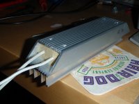
I'm a little bit nervous (paranoid?) about the best way to attach a load. I have two options: an old 8-ohm speaker from a 35w guitar amp, or a 100w 8-ohm resistor (see attached) for a dummy load. I thought I could run the resistor between two ice-packs and it would probably be okay for a couple of minutes. What do you guys think?
The speaker will burn up with constant power besides which you WON'T want to be in the room with it. The 100 Watt load will be fine with 100 or less Watts. you can likely overload it for short periods. It does take some time to heat it to the fail point. A few seconds at 200 Watts should survive with no additional cooling. Actively cooling it probably extends it considerably. How much? Don't know.
I don't have any problems running without a load at high levels for indefinite periods. It's not a good idea with transformer output amps but the vast majority of solid state amps have no output transformer so no problem. Switching on the load at full power probably isn't a good idea but it's been done many times with no harm.
As for the gain, I calculate it at 23 AND Adcom states the gain is 27dB, AKA 23.
G²
Okay, making a little progress here. I tested the good channel with my dummy load and it behaved very nicely. A good solid waveform, nearly identical to the input that was stable all the way up to full power. I can watch the waveform develop from a clipped sinewave to a nice smooth sinewave as I ramp up the Variac. It becomes properly reproduced (smooth, not clipped) at around 50-55% of full power (i.e around 60 volts).
One thing that is maybe still a little off is that with 1vac 60hz input, I measure 29.6vac output, which is significantly higher gain than the spec.
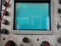
Onto the bad channel. Not pretty. With no load connected, as I ramp up the power, the trace appears like the good channel until I approach 50% on the Variac. At that point it starts to draw a lot of current and produces the attached waveform. At that point it's putting out about 3vdc at the speaker out. Then I get scared and shut everything down.
I'm not sure what that waveform means, being a 'scope noob, but I know it ain't right! (Just to be clear, the picture is showing the input signal trace on top and the output at the speaker terms on the bottom.)
One thing that is maybe still a little off is that with 1vac 60hz input, I measure 29.6vac output, which is significantly higher gain than the spec.
Onto the bad channel. Not pretty. With no load connected, as I ramp up the power, the trace appears like the good channel until I approach 50% on the Variac. At that point it starts to draw a lot of current and produces the attached waveform. At that point it's putting out about 3vdc at the speaker out. Then I get scared and shut everything down.
I'm not sure what that waveform means, being a 'scope noob, but I know it ain't right! (Just to be clear, the picture is showing the input signal trace on top and the output at the speaker terms on the bottom.)
Attachments
Last edited:
Okay, answering my own question again. I believe what I'm seeing is indeed oscillation in the bad channel. The picture shows it poorly, but the top of the sine wave turns "fat", I reckon as the output oscillates at some high frequency.
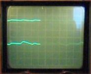
I then used the scope to compare ripple at V+ on each channel (no load, 1vac 50hz input). Sure enough, the bad channel has more ripple, and the waveform is irregular. (In the attached pic, the bad channel is on the bottom.)
Also, someone mentioned earlier that oscillation would cause R22 to overheat.
So, the $10,000 question is, what is causing the channel to oscillate?
Recall that originally, Q4 was bad (open), so the following parts were replaced:
Q4 and Q7 (matched at 258 and 222 hfe)
Q8 (415 hfe)
R7
R8
Attachments
So, the $10,000 question is, what is causing the channel to oscillate?
Recall that originally, Q4 was bad (open), so the following parts were replaced:
Q4 and Q7 (matched at 258 and 222 hfe)
Q8 (415 hfe)
R7
R8
Looks like a bad transistor or lost feedback loop before the output stage. Am not familiar with the schematic but maybe a low bandwidth driver or more likely lack of bias, low gain, or lost feedback in the last gain stage.
It seems that compensation is lacking in this amp.
A 68pF capacitor between base and collector of Q4
should tame down the oscillations.
A 68pF capacitor between base and collector of Q4
should tame down the oscillations.
It seems that compensation is lacking in this amp.
A 68pF capacitor between base and collector of Q4
should tame down the oscillations.
I disagree as I have one that behaves properly AND the other channel of Fred's unit works correctly as well. Rather than trying to improve on Nelson Pass's work, we should find out what it wrong with it.
Fred, if you want to send me transistors to run on the curve tracer, I'd be happy to do that and post/send you the photos when I return the transistors. Price is free as I'm curious as to what is going stupid on you.
G²
- Home
- Amplifiers
- Solid State
- Another high DC Adcom GFA-555