So when the amp first failed, the remaining channel (R), was playing just fine. Given my lack of experience, I think it will be very useful to have a good channel to compare readings with. So, I *think* the first order of business is to verify that the good channel is still good. To do that, it seems safest to disconnect the bad channel. What's the best way to do that? Is it enough to remove the fuses from the output boards or should I disconnect some leads?
Is this the right approach?
Remove both fuses from the bad channel and it will be disabled. There is a 3900 ohm resistor on each of the 4 main electrolytic caps but that really isn't sufficient load to verify the capacitors. That is a place where a 150 or 200 Watt bulb powered from the +82 OR -82 Volt lines would put enough load to really test the supplies. Test them 1 at a time (unless you use 2 bulbs). I don't really think that is your problem but having spent time trying to find a problem when it was 'simply' a power supply issue has me always checking power first. The minute or two to check sometimes pays off - often enough to check every time.
As I said earlier, the Adcom has separate bridge rectifiers and caps for each channel so it merits a few minutes to verify.
G²
Okay, baby steps...
I understand the principal of what you're saying, I think. You're saying to connect a load (150w bulb) across each 82 (my schematic says 81, btw) volt leg of each channel's power supply. Then I would measure the output with 'scope and DVM to ensure it is putting out + or - 81vdc with minimal ripple.
Mechanically speaking the way I think I would do that is to
1. remove the output/driver circuitry from the circuit by pulling the fuses
2. connect a 150w bulb across the + and - of one large electrolytic PS cap
3. use the variac to slowly bring up the circuit while watching the current to make sure it does not spike
4. where/how do I safely take my measurements? Just across the + and - of the cap?
Hi Glenn (EW),
Sure. It doesn't take me very ling at all. Are you counting the time to locate and install the correct lamp, and changing it as required?
I have used lamps. Not a fan. I will say they are far better than having nothing though. In a pinch, they can be a life saver, but I'll use my variac if you don't mind! 🙂
Hi djk,
I don't know how you could lose an output stage when using a variac. No current meter? My first was lacking a meter and I still didn't blow anything up. I still have that one come to think of it! The only amp I can think of that might do this would be a mosfet design with one or more open gate stopper resistors. That would be your fault in that case. Care to share?
There are some amplifiers that can latch, and others that simply has a sensitive voltage amp stage that won't work unless almost full voltage is applied. I consider those to be the minority of the amps you will run into. Amplifiers that have switching power supplies must be brought up in a modified way, but using a variac is a life saver with these. Stuff goes wrong really fast with a switching power supply! The Carver PM 2.0 is a perfect example of this. Just try and service this using a lamp! The Crown amps weren't too bad. I serviced many DC300A's with no problems using my variac.
One thing you must do if using a variac. Short the anti surge resistor out with a clip until the delay relay pulls in to short it. I can see where a lamp might allow it to burn out as well, depending on the wattage of that lamp.
I have witnessed amps that do all kinds of add things on a lamp limiting system, same for variacs too. Some Pioneer amps are bad this way, they draw excessive bias current until the voltage gets into the normal range. horrible design.
Hi Fred,
For bringing up old radios and other tube gear, the variac is the tool to use. It allows you to form the capacitor plates and limit the inrush current - avoiding damage. Still, the caps should be replaced. At least know you have a better idea of the unit's condition before spending a lot of money.
If you have a 5 ampere variac, I'd probably have used a 10 ampere meter. Use a breaker for fault protection. Fuses get mighty expensive (just ask me!). Anyway, a 5 ampere meter will work fine. It's just that you may slap the pointer against the stop as there is no headroom for current spikes.
To disconnect one channel of a stereo amplifier, use the fuses for that channel. That makes it easy. I expect your right channel is fine (operating). Do check the bias current after you've got the other channel repaired.
-Chris
Hi G²,
I don't understand why a lamp is involved here. Is this in the case where you don't have a variac?
-Chris
I don't understand why a lamp is involved here. Is this in the case where you don't have a variac?
-Chris
Still, the caps should be replaced. At least know you have a better idea of the unit's condition before spending a lot of money.
Maybe you mis-read me. I haven't tested anything yet because (a)I don't have the ammeter yet and (b) I'm unsure of the procedure.
I believe G2 was proposing the lamp to serve as a load to test the PS, but I am unsure as to how exactly one performs that test. (see post 142 above).
Hi G²,
I don't understand why a lamp is involved here. Is this in the case where you don't have a variac?
-Chris
No I want hime to put a several amp load onto the power supply to check the ripple with his scope. 2 amps at 80 volts is 160 Watts - a big and expensive resistor. A 150 or 200 Watt bulb will also get hot but it's supposed to so it won't be damaged and you can get them easily and cheap. That's all. Cheapo test load.
G²
No I want hime to put a several amp load onto the power supply to check the ripple with his scope. 2 amps at 80 volts is 160 Watts - a big and expensive resistor. A 150 or 200 Watt bulb will also get hot but it's supposed to so it won't be damaged and you can get them easily and cheap. That's all. Cheapo test load.
Well, I do have two 8 ohm, 100w resistors. What if I used those (to save a trip to the hardware to get the lamp!)? If I hooked them up in series it would be a 5 amp load, but 400w would probably damage the resistors, right?
I'm still not sure the right way to hook things up to do this test...
Last edited:
Hi G²,
Ahhh, got you.
Good idea. Look for the leading edge "pips". The bigger they are, the worse condition your capacitors are in.
One thing to check first though. Make sure you are not exceeding the ripple current rating when you do this. Every single ampere that you deliver from a power supply is ripply current through the capacitor. The spec sheets have a rating. Normal operation in an amplifier is fine at higher currents because the average draw is very much lower. I'm not sure what the ripple current rating would be on these.
Can you compare the value against new commercial capacitors Glenn? Just get the ripple current rating of new comparable capacitors to see what "normal" is before trying to do this.
Hi Fred,
81 VDC across 16 ohms will generate about 410 watts worth of heat. Not a good idea. "they were here for a good time, not a long time".
-Chris
Hi G²,
Ahhh, got you.
Good idea. Look for the leading edge "pips". The bigger they are, the worse condition your capacitors are in.
One thing to check first though. Make sure you are not exceeding the ripple current rating when you do this. Every single ampere that you deliver from a power supply is ripply current through the capacitor. The spec sheets have a rating. Normal operation in an amplifier is fine at higher currents because the average draw is very much lower. I'm not sure what the ripple current rating would be on these.
Can you compare the value against new commercial capacitors Glenn? Just get the ripple current rating of new comparable capacitors to see what "normal" is before trying to do this.
Hi Fred,
81 VDC across 16 ohms will generate about 410 watts worth of heat. Not a good idea. "they were here for a good time, not a long time".
-Chris
I just went to the DigiKey site and looked up some 15,000 uF 100V caps. Both the Panasonic T-HA series and Cornell Dubilier CGS series caps are rated more than 7 Amp ripple current so a 1-2 amp load shouldn't be a problem.
Since my Adcom is >20 years old now I might just try this on mine. I hope they're OK as even the 'cheapy' Panasonic caps are $28. The screw lug CDE caps are $49 per. Mouser has screw lug Mallory caps around $40.
G²
Hi G²,
Okay, right on! I wasn't sure what the specs were. So you're in the safe zone for sure.
It will be interested to see how your test goes. Can you capture scope traces or take a picture? I'd like to see what you see, and it will really help everyone else to know what to expect.
-Chris
Okay, right on! I wasn't sure what the specs were. So you're in the safe zone for sure.
It will be interested to see how your test goes. Can you capture scope traces or take a picture? I'd like to see what you see, and it will really help everyone else to know what to expect.
-Chris
I will be interested to see how your test goes. Can you capture scope traces or take a picture? I'd like to see what you see, and it will really help everyone else to know what to expect.
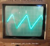
I will definitely do that, but I'm waiting on the ammeter before I do any testing on the amp. Meanwhile, I'd like to confirm I'm doing the test right and setting up the scope correctly. (When I'm sure I'm right, I'll write everything up into a procedure for future noobs, maybe I can add it to the forum as a wiki?).
Here's what I did:
- I used my Elenco XP-720 power supply for a test source. I set it up to put out 15 vdc into an 8 ohm load (big 100w resistor on a heat sink).
- I connected the scope probe (set to 10x atten.) and ground to the + and common of the PS.
- I set the scope coupling to AC. I set the AC gain to 10x.
- With volts/div set to .1/div and time/div set to 1ms, I obtained the wave-form in the attached pic.
If I'm reading it correctly, the wave-form shows approx. an 800hz, 250mv ripple.
Did I do everything correctly?
Attachments
I will definitely do that, but I'm waiting on the ammeter before I do any testing on the amp. Meanwhile, I'd like to confirm I'm doing the test right and setting up the scope correctly. (When I'm sure I'm right, I'll write everything up into a procedure for future noobs, maybe I can add it to the forum as a wiki?).
Here's what I did:
- I used my Elenco XP-720 power supply for a test source. I set it up to put out 15 vdc into an 8 ohm load (big 100w resistor on a heat sink).
- I connected the scope probe (set to 10x atten.) and ground to the + and common of the PS.
- I set the scope coupling to AC. I set the AC gain to 10x.
- With volts/div set to .1/div and time/div set to 1ms, I obtained the wave-form in the attached pic.
If I'm reading it correctly, the wave-form shows approx. an 800hz, 250mv ripple.
Did I do everything correctly?
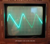
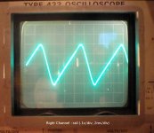
Close. Your supply is rated for 1 amp up to 15 volts. Your 8 ohm resistor with 15 volts would be 15/8 or 1.875 amps, well above the rated current. I'm surprised it's doing as well as it is. This little 'pips' are the regulator 'dropping out' at a 120Hz rate (North America). I predict if you stay in the ratings of the supply you will find nothing (or next to nothing) ripple wise.
The Adcom supplies aren't regulated and just show as 120Hz sawtooth that gets larger with the load. With a 150 watt lamp on the 80V supply the ripple is 250mV P-P.
G²
Hi Fred,
G² is spot on there. Now you know what a regulated power supply in crisis looks like! 🙂
Your scope setup is correct, always begin with a high volts / div setting and work down. Each and every time! Always remember that the setting will refer to volts per division and <unit time> per division, or square as you see the screen.
Nice scope.
-Chris
Thanks guys. That was educational! I hadn't seen any ripple at 5 volts fixed (as G2 predicted) so I switched the leads on the PS to 15 volts without remembering to redo the math for the load. So that's a number of useful lessons learned!
I think my scope may be older than me. And I'm not young.
I think my scope may be older than me. And I'm not young.
I use a variac and light bulb together at the same time when necessary.
For those who may not have considered the best of both worlds, I have used a light bulb and a variac at the same time. Some times an amplifier with a problem may allow you to get up to a fairly high voltage before "avalanching" current on you faster than you can turn the variac back down or cut the power off with the power switch.
25+ years ago I had an NAD 3020 integrated amplifier that would avalanche on me at about 55 volts AC. I couldn't properly diagnose it with a just a variac or just a light bulb alone. The light bulb would come on bright and the variac would be fine and all of the sudden "wham!" the current would max and blow the fuse and sometimes damage the unit under test even further as well. All this would happen in a very short range of just a few volts at around 55 volts AC. I have never seen anything like this before or since.
By running both a variac and a light bulb at the same time I have the best of both worlds. As a "test jig" I have also mounted switches to bypass (the variac) / short out (the light bulb) either one so that I can have just the variac or just the light bulb or even direct.
I have also used different sized bulbs 25W, 40W 60W 100W or even more depending on the size of the device being tested and the inrush requirements / limits I want. The little 20 watt a channel NAD 3020 only needed a 25W bulb but a much larger (huge?) Conrad Johnson requires several 100W bulbs in parallel to get past the "inrush hump" as I'll call it.
In post #143 anatech said:
"I have witnessed amps that do all kinds of add things on a lamp limiting system, same for variacs too. Some Pioneer amps are bad this way, they draw excessive bias current until the voltage gets into the normal range. horrible design."
Same here, I have seen lots of "weirdness" exhibited by perfectly good amps when under partial voltage. As concerning the low voltage high bias problem I have seen this repeatedly as well and didn't like those designs that do this. My solution was to ramp up more quickly and be ready to cut the power in an instant. This low voltage / high bias scenario is also a reason I instituted the variac with lightbulb solution.
Also in post #97 anatech said:
"These days you can use the On Semi parts and rest easy."
What On Semi part number(s) do you recommend for the driver transistors in the GFA-555?
Many thanks.
My Adcom (22+ years old) has all its original parts but if I needed to replace the outputs and drivers, I would look very hard at the MJE15032 (NPN) and MJE15033 (PNP) as the drivers. For outputs I'd likely use MJ15024 (NPN) and MJ15025 (PNP) devices. What I would not do under any circumstances is mix originals , in my case 2SB554 PNPs and 2SD42 NPNs with the ON semis. I would replace drivers as a pair if needed and ALL the ouputs as a group. I likely wouldn't bother matching devices and in the event of subsequent failure, I would not replace all outputs as a group but only the 1 or more likely 2 devices. I have never seen parallel transistors ALL fail together. One device dies and disables and protects the remaining devices in the NPN or PNP group. Almost always 1 device from each group fails. As long as the part number is the same, I'd only replace the bad devices. Because I have a curve tracer I'd probably look at the rest of the devices and if something seemed quirky I would change it.
I've been working on some mid 70's broadcast gear that has had silicone grease dry up. Re-greasing the power devices on old equipment seems like a good idea to me and certainly checking the mounting screws on power transistors and filter caps be firmly snugged up. No I don't know how many inch-ounces I tightening but I have a pretty good feel after 40 years (I started in high school)
G²
Hi cbottorff,
Never had a problem with the NAD units, aside from my low opinion of the design. With these and many other units that were "funny" on power up, I just monitor a few key points to see what they are doing as the voltage increases. I may run just the amplifier section only on a DC power supply, depending on how I feel about the situation. If it's only a "design feature", the unit gets powered up on the variac and I scoot by the problem area.
Units like these must be fun if plugged into 120 VAC and meant for 240 VAC, or in a brownout. Nice design work! You figure these guys actually studied engineering somewhere too. The obvious units to handle differently are those with any type of input power regulation. This would include some Sony and Yamaha units, and also most Carver amplifiers. They will, by design, draw high current at some point, and then settle into their normal low current selves. Computer power supplies are another example of this type of supply, I'm sure there are no shortage of examples here.
The examples above show why a trained technician with experience can make all the difference in the world to the success of a repair.
The On semi devices to look at are the ones with the same case style as the original, and specs that exceed the original. Not really too difficult. For output transistors, I would be looking at MJ21195 and MJ21196. These tend to be close in beta, whereas the MJ15022 ~ MJ15025 are not. A careful cleaning with new thermal compound and mica insulators to finish the work.
Hi G²,
I agree with most of what you say, except that matching the outputs does give lower distortion numbers. For years my customers have commented on improved sound quality and it tool me a bit to clue into what I was doing to cause this. Always replace dead parts back and including the first good ones you measure / find. They didn't blow, but consider them possibly stressed. For the money? Change 'em out.
Guess what I'm going to say about one or two blown transistors in an output stage? Change them all again !!! Each instance of a blown output stage should be treated as a new repair. You missed something - right? Excessive current did flow in places it shouldn't, and all outputs may have been stressed. Example, one NPN device blows in a complimentary design. Never assume best case, always assume the worst. Assume the entire mess was cooking and one actually let go. They were all operating beyond the second breakdown limit somewhere, so damage probably occurred on all dies to some extent. Leakage may increase, active areas reduced in size or even cracks in the die. They may fail at a later date. So, remove all of them, and put them into the garbage! You can't trust them.
Okay, back to our shorted NPN device. Let's say we are optimistic and this one device was defective (What? You didn't test them first for gain and leakage?). In the instant things went sideways, a number of events took place. Since failures and fuses are typically thermal events, some time went by - a lot for the semiconductors. The NPN up and shorts, perhaps a voltage breakdown so it's nice and sort of sudden. This is your best case failure people. Now that transistor is a mighty fancy looking piece of heavy wire with very low resistance. The power supply is now directly connected to the speaker output buss and nothing will now change this, unless an emitter resistor opens (which will bring the base line high, kill the driver through reverse bias and cook all the other NPN transistors). The differential pair (or whatever) is a control freak. It didn't command the output to change it's DC level, and it's mighty put out no one asked for it's permission. So in a mighty snit, it tells the NPN stage to back off and the PNP stage to begin conducting - hard. There is no feedback anymore as all the surviving devices are either in cutoff or in saturation, so everything gets pushed completely on or off. The NPN control doesn't give a hoot, it's doing it's own thing. Conduction continues without interruption. New to this party are all those fun loving PNP guys. Tug of war, great! They are on full, each determined to be as like a piece of wire as they can possibly be. The power supply voltages begin to drop, not even one half cycle of the AC power has completed yet - not even close. So the supplies now are conducting current limited only by two things I can think of. The resistance of the wires, transistors (close to 0.1 ohms for argument) and those poor emitter resistors. The emitter resistor for the NPN part is probably going to open first, it's 4 against 1 (or 5 against 1). The PNP parts have gone past the point of no return as the silicon heats past the 150° to 200° temperature to reach melting points of bond wire and other good stuff. The die probably cracked from the temperature gradient. So they are now ... wire also (probably, anything can happen now). Now the NPN emitter resistor opens, causing at least reverse breakdown to occur from emitter to base, or the dead one is shorted. All other base connections are now connected to the supply rail if they weren't already. Cool! 😎
To be honest, who cares what happens next? At some point, fuses will begin to open, but that point is still far into the future in this time scale. No smoke has yet escaped from anything, current meters have not yet reacted, nor has the speaker protection network. You have not yet observed or heard anything. The destruction will continue, copper traces heat up and burn solder mask. Later, they are so hoe that the bonding agent completely fails and the traces lift off the substrate as they reach incandescence. Some resistors may also be reaching temperatures that emit light as transistor cases (the smaller ones) crack open issuing solder or other stuff. At this point, material is beginning to accelerate away from it's origin. You haven't yet sensed anything is wrong, fuses are still intact.
If you ask me, all those parts are scrap, at least until you start finding good parts, the first good parts are highly suspect.
So. Who here will stake their reputation on parts that were abused like this? If you don't care about your reputation, how about the amount of work it will take you again at some point in time? I think there is a problem with the definition of a "good part" and what that really means.
-Chris
Hi cbottorff,
Never had a problem with the NAD units, aside from my low opinion of the design. With these and many other units that were "funny" on power up, I just monitor a few key points to see what they are doing as the voltage increases. I may run just the amplifier section only on a DC power supply, depending on how I feel about the situation. If it's only a "design feature", the unit gets powered up on the variac and I scoot by the problem area.
Units like these must be fun if plugged into 120 VAC and meant for 240 VAC, or in a brownout. Nice design work! You figure these guys actually studied engineering somewhere too. The obvious units to handle differently are those with any type of input power regulation. This would include some Sony and Yamaha units, and also most Carver amplifiers. They will, by design, draw high current at some point, and then settle into their normal low current selves. Computer power supplies are another example of this type of supply, I'm sure there are no shortage of examples here.
The examples above show why a trained technician with experience can make all the difference in the world to the success of a repair.
The On semi devices to look at are the ones with the same case style as the original, and specs that exceed the original. Not really too difficult. For output transistors, I would be looking at MJ21195 and MJ21196. These tend to be close in beta, whereas the MJ15022 ~ MJ15025 are not. A careful cleaning with new thermal compound and mica insulators to finish the work.
Hi G²,
I agree with most of what you say, except that matching the outputs does give lower distortion numbers. For years my customers have commented on improved sound quality and it tool me a bit to clue into what I was doing to cause this. Always replace dead parts back and including the first good ones you measure / find. They didn't blow, but consider them possibly stressed. For the money? Change 'em out.
Guess what I'm going to say about one or two blown transistors in an output stage? Change them all again !!! Each instance of a blown output stage should be treated as a new repair. You missed something - right? Excessive current did flow in places it shouldn't, and all outputs may have been stressed. Example, one NPN device blows in a complimentary design. Never assume best case, always assume the worst. Assume the entire mess was cooking and one actually let go. They were all operating beyond the second breakdown limit somewhere, so damage probably occurred on all dies to some extent. Leakage may increase, active areas reduced in size or even cracks in the die. They may fail at a later date. So, remove all of them, and put them into the garbage! You can't trust them.
Okay, back to our shorted NPN device. Let's say we are optimistic and this one device was defective (What? You didn't test them first for gain and leakage?). In the instant things went sideways, a number of events took place. Since failures and fuses are typically thermal events, some time went by - a lot for the semiconductors. The NPN up and shorts, perhaps a voltage breakdown so it's nice and sort of sudden. This is your best case failure people. Now that transistor is a mighty fancy looking piece of heavy wire with very low resistance. The power supply is now directly connected to the speaker output buss and nothing will now change this, unless an emitter resistor opens (which will bring the base line high, kill the driver through reverse bias and cook all the other NPN transistors). The differential pair (or whatever) is a control freak. It didn't command the output to change it's DC level, and it's mighty put out no one asked for it's permission. So in a mighty snit, it tells the NPN stage to back off and the PNP stage to begin conducting - hard. There is no feedback anymore as all the surviving devices are either in cutoff or in saturation, so everything gets pushed completely on or off. The NPN control doesn't give a hoot, it's doing it's own thing. Conduction continues without interruption. New to this party are all those fun loving PNP guys. Tug of war, great! They are on full, each determined to be as like a piece of wire as they can possibly be. The power supply voltages begin to drop, not even one half cycle of the AC power has completed yet - not even close. So the supplies now are conducting current limited only by two things I can think of. The resistance of the wires, transistors (close to 0.1 ohms for argument) and those poor emitter resistors. The emitter resistor for the NPN part is probably going to open first, it's 4 against 1 (or 5 against 1). The PNP parts have gone past the point of no return as the silicon heats past the 150° to 200° temperature to reach melting points of bond wire and other good stuff. The die probably cracked from the temperature gradient. So they are now ... wire also (probably, anything can happen now). Now the NPN emitter resistor opens, causing at least reverse breakdown to occur from emitter to base, or the dead one is shorted. All other base connections are now connected to the supply rail if they weren't already. Cool! 😎
To be honest, who cares what happens next? At some point, fuses will begin to open, but that point is still far into the future in this time scale. No smoke has yet escaped from anything, current meters have not yet reacted, nor has the speaker protection network. You have not yet observed or heard anything. The destruction will continue, copper traces heat up and burn solder mask. Later, they are so hoe that the bonding agent completely fails and the traces lift off the substrate as they reach incandescence. Some resistors may also be reaching temperatures that emit light as transistor cases (the smaller ones) crack open issuing solder or other stuff. At this point, material is beginning to accelerate away from it's origin. You haven't yet sensed anything is wrong, fuses are still intact.
If you ask me, all those parts are scrap, at least until you start finding good parts, the first good parts are highly suspect.
So. Who here will stake their reputation on parts that were abused like this? If you don't care about your reputation, how about the amount of work it will take you again at some point in time? I think there is a problem with the definition of a "good part" and what that really means.
-Chris
OK, I'll defer to your experience. It's been a LONG time since I worked on audio gear on a regular basis. My 'power amps' are used for motor drives in broadcast video tape machines. The circuitry of an analog MDA (Motor Drive Amplifier) is eerily similar to audio amps but for motors we really could care less if there is a bit of 'distortion'. If you can repair an audio amp you can certainly make an MDA work properly. BTW, MDAs fail very rarely and the last one I worked on a few weeks back (over a year before that) likely failed because the screws holding the TO-3 device weren't tight and it overheated 1 of the 4 parallel devices. It was a 'the client is waiting' deal and I didn't check too much but got it back on line quickly and with all snug screws. That MDA last failed about 13 years ago and I was the repair guy then. It made it past the warranty period.
G²
Hi G²,
In the case of motor drives, I can't disagree. They generally do not use any bias current, and emitter resistors force current sharing at the high load currents (same for audio power amps). In your case, no complaints. I did a few Studer machines for motor drive circuits. They mount them dry with mica insulators, how about that?
Clients waiting in the video or audio studio business are never fun either. We all hate those situations.
-Chris
Wow, Chris, that was a cool blow-by-blow of a circuit failure. I hope James Cameron does the movie version! 🙂 And I hope that's not the fate that awaits this amp... Yes, best not to think about that.
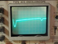
Back on track. Finally able to do the PS testing. Here's how I set up the test:
1. Disconnected the output section by pulling the fuses
2. Connected my scope and a 150 watt bulb (as a load) across the + and - terminals of each power supply cap. The scope was set to AC coupling and ranged to .1v/div and 2ms/div. The probe was set to 10x and the 10x gain on the scope was on.
3. Ran up the power to full voltage.
The result was the attached traces. Also, with the DVM each supply measured about -/+76vdc under load and 84vdc without a load. The amp pulled about .5 amp under the load, btw.
I think I'm seeing something similar to what G2 described in #152, except this is a 125hz, 400mv p-p ripple. Am I reading the trace wrong or is my ripple nearly twice his?
In any case, I think I can safely conclude my PS is okay. Do you guys agree?
What's my next move?
Attachments

Last edited:
- Home
- Amplifiers
- Solid State
- Another high DC Adcom GFA-555