The M2 rod and drill guide is perfect. Now I need to figure the best way to machine a ball bearing set in the end of the RC65 metal.
The Drill rod should only be surfaced hardened so drilling with a center drill should work. I used a 5mm SI3N4 ball and sunk it about 30% into the spindle. If the spindle is hardened all through use a solid carbide bit.
To ensure rotation is concentric drilling for the ball must be done in a 4 jaw chuck so you can clock the spindle in to ensure the ball is centered. You need to ensure both planes are concentric use a DTI at the chuck and then move the indicator to the end and make sure the spindle is not skewed. My current spindle was done in a high accuracy collet chuck.
The biggest challenge I had was reducing vertical runout on the platter. I ended up mounting the rotor on a spindle in a collet block and grinding the platter mounting face to true it up to the axis of rotation. Platter vertical runout is now better than 0.02mm at the outer edge.
It took months of trial and error to get platter rotation this stable. I was lucky to have a Goldmund Reference on hand as a benchmark.
Thanks for that. I may have to do the machining at the university maker space where they have very nice lathes and a experience machinist to consult with.
Or........I can go with the maglev concept dispense with all this vertical support stuff.. 😉
Or........I can go with the maglev concept dispense with all this vertical support stuff.. 😉
I would just get a solid carbide center-drill anyway.If the spindle is hardened all through use a solid carbide bit.
jeff
It seems like a good solution would be to simply buy?
https://tng-spinner.com/products-de...=VHL BEARING SLEEVE WITH ISOLATING DAMPER CAP
https://tng-spinner.com/products-detail.php?id_pro=36&producto=ZIRCONIA HI-LUBE SUBPLATTER
https://tng-spinner.com/products-de...=VHL BEARING SLEEVE WITH ISOLATING DAMPER CAP
https://tng-spinner.com/products-detail.php?id_pro=36&producto=ZIRCONIA HI-LUBE SUBPLATTER
Here's a little note on ball bearings.
It's typical that a precision metal ball bearing will have lower overall sphericity than a carbide or nitrile ceramic ball. But, on the microscopic level the metal ball is smoother, think of it as having sinewave surface deviation vs the ceramic ball having triangle wave surface deviation. Add this to the hardness difference and that's why ceramic balls wear out thrust pads and shaft ends faster.
You can test this at home with a simple 4-ball kinematic cradle, the ceramic version will have much higher stiction. I made a couple of kinematics bearings with carbon arm tubes attached and the metal versions had much lower stiction.
I could deflect the tonearm on the metal version holding a 20 x 5mm strip of fag paper, (rizzla blue) the ceramic rig need a piece of paper 20 x 20mm to deflect it, so 4x more stiction.

That's a very interesting comment comparing metal and ceramic balls. But I particularly like the Rizla blue test methodology! Wonderful.
I note the WB has announced that the new kinematic bearing on the new GMT deck uses a mix of steel and ceramic in the bearing.
If someone has limited tools, would an expanding reamer be a practical way to get a bush to it's final size? Never actually used one.
@cracked case An off the shelf reamer is not accurate enough especially in a cheap Chinese lathe. I have a good old Pommy Colchester, I tried reaming and was over size due to 5microns of runout in the collet. The best way to machine accurate bushes is to do OD and ID in one operation. I do OD and undersize ID then fit the bush and clock on the ID ensuring the sleeve is down the thrust line of the lathe, this way takes a lot more fiddling with setup and a micron indicator and bore the bush very carefully. One slip and its a new bush.
An SP10mk2 bearing has about 23microns clearance 30microns and its sloppy.
An SP10mk2 bearing has about 23microns clearance 30microns and its sloppy.
I've heard that if you use a reamer at high speed it will make a larger hole than at low speed; so perhaps if you hand turned the chuck, or perhaps if you Colchester has a two speed motor it will go down to 34 RPM (I've used them a lot) it would work, however this might only work for negative rake reamers. An expanding reamer would just be adjusted to a smaller size.
I use a very expensive and accurate adjustable hand reamer and work my way up in very small steps.
It ain't that easy but it woks very well.
Reaming on the lathe is doable but you need to run at low speed.
It ain't that easy but it woks very well.
Reaming on the lathe is doable but you need to run at low speed.
I also have used a hand reamer with very good results. I ream to slightly tight and then hone to increase clearance in 0.0002" increments. My approach is to start with precision drill rod, +0.0000, -0.0005" and then make the bushing to match. I have finished one and it "feels" very good. I still have to test mount it and test it. My test breadboard is for this is still being built.
If you ream on the lathe you will get an outsized hole unless your tail stock is perfectly aligned. I discovered that from experience and my tail stock is now much better aligned, but I wouldn't say it was perfect. Very gentle hand reaming with plenty of lubricant is likely to give a better result.
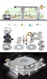
My 2 cents for those who, like me + some of us, do not have "toolroom machines" and, more, the adequate skill to use them.
(Sorry, no micron tolerances, just matching, ending with 1/10mm ca wobble and eccentricity on platter edge, measured)
First - be wary of AliBay claims: to avoid some previous diy disappointments in turning spindles, this time I bought a HSS rectified rod, "lab grade" = bent, for bananas measuring? dumped. And I had the 40mm plexy platter CADCAM precision laser cut by a well known workshop (sounds hitech, isn't it?) = slanted + offset laser cuts.
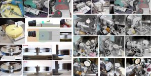
So, landing on earth. For the spindle I had to turn it myself from scrap on my ol' rubber BV20 lathe = never, never remove the spindle from the chuck, to get it true. But, after the lapping, the "perfect" spindle was a few cents undersized. So I simply cut the sintered bushing diagonally. Together with an accurate mating of the ball + seat materials (various trials), with some tuning all works fine to have a really quiet spindle. (stetho)
For the second one, the crooked platter, I had to center and rectify it carefully by blueing + that simple gadget = two days spent + lots of dust to breath
carlo
hope photos are clear - that's all, folks
(Sorry, no micron tolerances, just matching, ending with 1/10mm ca wobble and eccentricity on platter edge, measured)
First - be wary of AliBay claims: to avoid some previous diy disappointments in turning spindles, this time I bought a HSS rectified rod, "lab grade" = bent, for bananas measuring? dumped. And I had the 40mm plexy platter CADCAM precision laser cut by a well known workshop (sounds hitech, isn't it?) = slanted + offset laser cuts.
So, landing on earth. For the spindle I had to turn it myself from scrap on my ol' rubber BV20 lathe = never, never remove the spindle from the chuck, to get it true. But, after the lapping, the "perfect" spindle was a few cents undersized. So I simply cut the sintered bushing diagonally. Together with an accurate mating of the ball + seat materials (various trials), with some tuning all works fine to have a really quiet spindle. (stetho)
For the second one, the crooked platter, I had to center and rectify it carefully by blueing + that simple gadget = two days spent + lots of dust to breath
carlo
hope photos are clear - that's all, folks
Attachments
- Home
- Source & Line
- Analogue Source
- Another DIY turntable bearing thread