Hi Guys
take a look at Magnet felt oversigt
You can download FEMM files by clicking in the first columen; 1a, etc.
All simulations are done looking down from the top of the ribbon and showing tangential field. Also you need to increase the number of simulation points. Fields should be nice and round - not jagged.
Hello ,
how about attaching your unsolved *.FEM file to your next post so we can take a closer look on the subject?
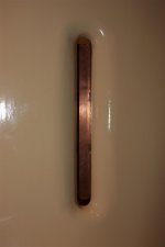
I attached a simple simulation to this post. This is a view from the top. The ribbon must lay flat between the two magnets. The alternative current passing through the ribbon will push it in and out, perpendicular to the plane (z axis).
I am still very sceptical about introducing gaps as a solution to gain more flux , sounds too easy .
The only way to find out is to build one.
You should have noticed already that the ungapped variation to the left in your pic is completely wrong , it shows constant flux across the gap width , which is not possible physically without special treatment .
A simulation with 90deg rotated view looking from the top will show you a more realistic impression of the field distribution , stronger to the sides and weaker in the middle .
The reason why the simulation shows a constant flux across the gap width (assuming here that you mean the ribbon gap) is because of the length (y axis on the simulation) of the magnets. The longer the magnets, the more uniform the magnetic field is along the x axis in the ribbon gap. As I mentioned previously, the magnetic field becomes weaker with longer magnets. See my attached simulation.
Doing so gives two different results with the same (limited) 2D FEA analysis program , which one is "correct" ??
Decide by yourself ...
None is correct. As you mentioned, it is only a 2D simulation. As far as I know, there is no 3D simulation software that is freely available.
PS: In FEMM, one can specify the depth (in the problem definition box). Unfortunately, changing this parameter does not seem to have any effect on the computed magnetic fields.
Attachments
Hello ,
I am still very sceptical about introducing gaps as a solution to gain more flux , sounds too easy .
I have built two small magnetic systems. I discovered that the magnetic field next to the magnet and next to the gaps filled with steel have opposite directions. Thus introducing gaps is not a good idea.
Bruno
gaps filled with steel
I reckon steel in the gaps will short the magnets 🙁
its funny, but when sliding the magnet on the iron backpole, you can easily feel when it gets stronger attached to the steel, thus getting stronger, I suppose
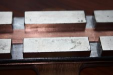
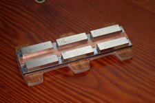
At the moment its about 5-6mm gaps at magnet ends
I reckon steel in the gaps will short the magnets 🙁
its funny, but when sliding the magnet on the iron backpole, you can easily feel when it gets stronger attached to the steel, thus getting stronger, I suppose
At the moment its about 5-6mm gaps at magnet ends
I observed a repulsion without steel as well.
Hi Brunob.
It is a little late,but here are more simm`s.

Here is the drawing.


Here is a graph that shows field along the red line.As you see it goes both + and-

This one is without steel in the gaps.
It is a little late,but here are more simm`s.
Here is the drawing.
Here is a graph that shows field along the red line.As you see it goes both + and-
This one is without steel in the gaps.
Hi Brunob.
It is a little late,but here are more simm`s.
Hi båndsei,
thanks for the simulations. It is nice to see that the simulations confirm what I observed: reversal of the polarity at the gaps. I have to admit that if I would not have observed this effect, I would not have believed it ! FEMM is a nice piece of software.
Bruno
When trying to butt the magnets together on a steel backing plate , they tend to want to repel confirming what you say, it does not affect the field strength when measured ...
I dont understand why the field show reversed polarity at magnets ends gap
And neither do I understand why it shows as having even stronger field there as well
Well, it may seem more likely with the back pole iron "streching" through end gaps to the front pole
But with air gap it would seem different
Makes me wonder whether the backpole iron should be sliced/cut at magnet ends gap
Maybe its the backpole iron causing the polarity reversal
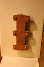
Though, I have the iron back pole iron mounted as in planars
and with copper as well
maybe that makes a difference
And neither do I understand why it shows as having even stronger field there as well
Well, it may seem more likely with the back pole iron "streching" through end gaps to the front pole
But with air gap it would seem different
Makes me wonder whether the backpole iron should be sliced/cut at magnet ends gap
Maybe its the backpole iron causing the polarity reversal
Though, I have the iron back pole iron mounted as in planars
and with copper as well
maybe that makes a difference
Attachments

When trying to butt the magnets together on a steel backing plate , they tend to want to repel confirming what you say, it does not affect the field strength when measured ...
If you would have field strength measurements to share, that would be very interesting.
Cheap and more expensive tools to measure magnetic fields:
Gaussmeters for Measuring Magnetic Fields
Gaussmeters for Measuring Magnetic Fields
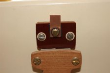
Regarding field reversal between magnet ends
I have tried with a compas
It shows no other than a slightly bending field, but no reversal
Compas method may have flaws tho
Then I tried with a very small magnet
It appears that there may be something like a null between magnet ends
Certainly not reversed field
Or at least it is very weak
My conclusion is that the possible reversed fiel causes a near null effect, but certainly not a strong reversed field as suggested and shown by sims
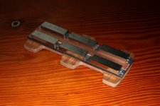
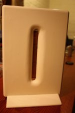
Or at least not in design shown below
I claimed earlier that theres a general increase in magnet field with slighter greater gap at magnet ends
My theory is now that the null effect is there, and its spread remains the same, no matter how big your end gap is
With magnet ends closer together the null effect spreads into the magnet
Hence you get a slightly weaker field, instead of a null effect
I have tried with a compas
It shows no other than a slightly bending field, but no reversal
Compas method may have flaws tho
Then I tried with a very small magnet
It appears that there may be something like a null between magnet ends
Certainly not reversed field
Or at least it is very weak
My conclusion is that the possible reversed fiel causes a near null effect, but certainly not a strong reversed field as suggested and shown by sims
Or at least not in design shown below
I claimed earlier that theres a general increase in magnet field with slighter greater gap at magnet ends
My theory is now that the null effect is there, and its spread remains the same, no matter how big your end gap is
With magnet ends closer together the null effect spreads into the magnet
Hence you get a slightly weaker field, instead of a null effect
Attachments
I must agree with you Tinitus .I have just done a test that shows the same.I have been confused by the 3.dimension.Sometimes you see what you want to see.
I made 2 tests.The first with the end of a magnet held tangentialt to the rows and it repelled in the gaps and atracted at the magnets,but as i tried with a thin aluwire supplied with DC. it shoved that there was no differece regarding gab and magnets.
Sorry for my wrong simms,but glad that i dont have to change my magnetsystems.
Bernt "bånd"
I had a small Gauss meter and at the time and it did appear best to butt the magnets and not have a gap.. A small gap did not appear to affect the field strength, i wanna believe the magic number was 6 MM , it did over this amt if my recall memory is right .... 😛.
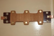
Funny, yesterday I grapped the assembled magnet design shown above with one hand, and I clearly felt a strange tickling in my fingers
A bit scary
A bit scary
Funny, yesterday I grapped the assembled magnet design shown above with one hand, and I clearly felt a strange tickling in my fingers
A bit scary
What imaging already ......... 😛
Attachments

- Home
- Loudspeakers
- Planars & Exotics
- Another DIY Ribbon thread