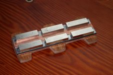
Measures of my first ribbon tweeter
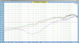
Here are the frequency responses of the tweeter shown in my previous post.
0) blue line, kind of reference, I used a UR2 ribbon tweeter
1) red line: no steel bars
2) green line, two steel bars on the side of the magnets
3) four steel bars (loop).
With the steel bars. the sensitivity is about 2.5 db higher at 1 KHz.
Bruno
Attachments
very cool,thats quite a jump in efficiancy just by containing the magnetic flux in its own circuit using the steel bars. jer
very cool,thats quite a jump in efficiancy just by containing the magnetic flux in its own circuit using the steel bars. jer
Actually, I was hoping for a higher increase in efficiency. 2.5 db is not that much. The FEMM simulations I made show a very high increase of the magnetic field in the ribbon gap when a steel bar loop is used.
The magnets I used are here: supermagnete.de - Q-40-10-10-N: Block 40 x 10 x 10*mm
Bruno
The loop you made is not right.You got to have the ironbars behind, and not top and buttom.In FEMM you see a crossektion.Hope you understand what i mean.
yes,I undestand but it shows that it is an increase nevertheless.
More than I realized compared to no magnetic circuit at all as 3db shows about a 50% increase in field strength ,if I'm not mistaken.
Keep up the good work.
Please post your results and different and/or better configuration aswell.
Very interesting. jer
More than I realized compared to no magnetic circuit at all as 3db shows about a 50% increase in field strength ,if I'm not mistaken.
Keep up the good work.
Please post your results and different and/or better configuration aswell.
Very interesting. jer
Last edited:
yes,I undestand but it shows that it is an increase nevertheless.
Might be because iron will act as a soft "blocker" to the mag field
It kind of "pushes" the field strength in the opposite direction, where its needed
If you ad some copper between iron and magnets, the effect gets even stronger
oh, I forgot, its what you know as "magnetic shield" ..... and its different from "shorting" the back field with iron, which attempts to "direct" the back field
Attachments
The loop you made is not right.You got to have the ironbars behind, and not top and buttom.In FEMM you see a crossektion.Hope you understand what i mean.
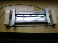
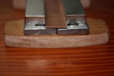
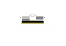
I put two steel bars behind, as shown in the picture below.
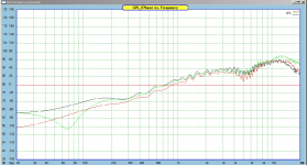
The measurements:
red: no steel bars,
green: side steel bars
black: 2 more steel bars behind (as in the pict)
Conclusion: behind is not as good as top + bottom.
But then, I am not sure to have understood what you meant.
Bruno
Attachments
This page shows another topology (horse shoe?) for increasing the magnetic field in the gap: Ribbon speakers - DIY.

Its a way to have a narrow small gap, with BIG magnets
Just like we know it from ordinary dynamic speakers
Other than that I doubt theres enough other benefits to substantiate the increased difficulty, and cost
Iron means magnetic losses too
Just like we know it from ordinary dynamic speakers
Other than that I doubt theres enough other benefits to substantiate the increased difficulty, and cost
Iron means magnetic losses too
Alain Engineering (e-speakers.com), know as BEEngineering in Europe, uses a cylinder steel rear surround to complete the magnetic field and provide adequate rear-ribbon volume for extensive sound absorption material to dampen rear ribbon wave reflections.
The two NdFeB block magnets are up front next to the ribbon and form the two pole pieces. Since steel saturates at 1.5-1.7T, using steel next to the ribbon for the pole pieces will create a lower magnetic field than using NdFeB block magnet pole pieces. Large lower strength ceramic magnetics sometimes were put behind large tapered-tip steel pole pieces in order to concentrate the field into the gap at the saturated 1.5T level.
Alain also sells an 3-ribbon MTM design that stacks these cylinder structures. Cost: a few thousand dollars per ribbon.
Attachments

Ahh, nice pictures 🙂
I have seen those ribbons before, but didnt know it was like that
Its a neat design to use a round thick steel tube
But actually it looks more like a planar tweeter 😕
Looking again it appears like theres two flat leads on diaphragm
One magnet on each side, an one magnet in the middle
Looks quite doable🙄
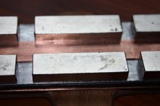
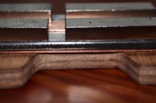
My new ribbon magnet system 🙂
Looks nice.
What is the size of the magnets?
Is there a particular reason to leave a gap between the magnets?
Bruno
5 microns Aluminium foil
I would like to measure the same ribbon tweeter with 9 and 5 microns thick aluminum foil.
Does anyone know where to find 4 to 5 microns foil?
Thanks,
Bruno
I would like to measure the same ribbon tweeter with 9 and 5 microns thick aluminum foil.
Does anyone know where to find 4 to 5 microns foil?
Thanks,
Bruno
Member
Joined 2003
I used 5 micron in my ribbons...believe it originally came from a film/foil cap winding facility. I also remember seeing a company in Germany producing it, but can not remember specifics...it has been too long.
Looks nice.
What is the size of the magnets?
Is there a particular reason to leave a gap between the magnets?
Bruno
thanks
magnets are 1/4 x 1/2 x 1.5"
magnetized through thickness
I got them free from a friend, so the design is random and not that well planned
I consider it experimental proto
I have added a second copper layer (farraday), seperated with cardboard
Seems to give a small improvemnet in strength, and more flattened field shape
Attachments
Is there a particular reason to leave a gap between the magnets?
Bruno
Good question
Well, if the magnets are forced closer together(ends), it appears to me like the general field gets weaker
I cant prove it tho
It also seems like there could be an optimal minimum/maximum gap size
Meaning that a very narrow field gap has no advantage in field strength
Good question
Well, if the magnets are forced closer together(ends), it appears to me like the general field gets weaker
I cant prove it tho
It also seems like there could be an optimal minimum/maximum gap size
Meaning that a very narrow field gap has no advantage in field strength
I think that is a very good idea! I made some simulations with FEMM. Woaw. I got an increase of the magnetic field from 0.20 to 0.73 tesla!!!!
More details later. I still have to find the optimal gap size.

- Home
- Loudspeakers
- Planars & Exotics
- Another DIY Ribbon thread