I am very glad to see that all of you made ribbons, and they look very good. Keep up with excellent work!
In the meantime, i didn't give up of ribbons, i am just waiting to find mylar. I want to build 4Ohm speakers (4-5 alu stripes on mylar), and eliminate problem with transformer. I was perfecting my design and now i have very good field in simulations, which will give me ~90dB@1w@1m.
In the meantime, i was wondering why we should coagurrate alu foil? If the field is uniform enough then we can put flat foil instead.
Look at this site http://www.raalribbon.com/. Those are ribbons made in my country, but the point is in their flat foil. If the ribbon is flat maybe it will produce less distorted sound, because of parallel magnetic vectors.
Member
Joined 2003
Thanks for the link Mx...I hadn't see the RAALS before.
While building my prototype ribbons, I experimented with pleated, flat, and textured ribbons.
I didn't find any really large differences among the three types but the flat ribbons were somewhat "touchy" to adjust to avoid resonances. Texturing the ribbons helped to kill resonances (as I believe RAAL does). Pleated ribbons tended not to twist when driven hard at low frequency, showed lowest resonances, and seemed the best overall compromise for my application. Though the flat and textured were certainly easier to prepare 5' long, when overdriven, they tended to twist 90 degrees in a long/tall gap and showed more tendency to ring.
Verhagen discusses the three ribbon types in his book, so you may want to check that out. He does demonstrate that pleated is the least efficient (because of higher mass) but, as always, there are other compromises to be considered.
What I find most interesting about the RAALS is using acoustic resistance to shape vertical directivity.
Paul
WTW ribbon project
I have also used FEMM and found few things that you should think when simulating with it.

1) Always draw ribbons "from up to down" since this is 2D simulation tool. Someone told this in previous posts too. My opinion is that if you get near 1T fields in the middle of air gap or linear field, you are doing it all wrong 🙂
2) Something new: You can still try to simulate crossbars. Draw a crossbar. It width should be DH/(L+H), where
D = real crossbar depth
H = real crossbar height
L = real airgap height between crossbars.
Since 2D simulation acts like infinite deep model, this DH/(L+H) has the same area for flux that the real crossbar and metal saturation will be taken into account.
Next draw a crossbar as far away from the air gap as possible so that it reacts with field in the air gap as little as possible. To do that, you naturally need to increase crossbar length and make it look like f.ex. a half circle. But you can do it. It doesn´t need to look right. Crossbar in a simulation only model extra flux caused by crossbar. Nothing else. That "half a circle" is longer than real crossbar since magnetic flux from the middle of air gap height travel first along side bars and average flux path is longer that crossbar length.
So total crossbar length in simulation could be someting like L/4+C, where C = length of real crossbar. This is just my first approximation. Someone could try to define this more precise 🙂
You can even split crossbar into two bars. One in front and second in back to make model symmetric as well as magnetic field in air gap.
3) FEMM is just a simulation tool that use numeric methods to calculate something. It´s achille heel is sharp corners. You have propably noticed that even if your model is symmetric, your results are not exactly that. Try to round every corners a bit. Then FEMM add points to corners and can simulate more precise.
Make a test: Simulate symmetric model without roundings. Then start to round every corner and increase round radius. What is the radius when magnetic field is symmetric and doesn´t change any more even if you increase radius a bit? Even with small radius results can be much different than original. Why. They are more precise. 🙂
I just ordered the book on ribbons and I will definitely build one.
I like the one from Michael Gaedtke because I can find the same parts.
I like the one from Michael Gaedtke because I can find the same parts.
APi said:I have also used FEMM and found few things that you should think when simulating with it.
....
Since 2D simulation acts like infinite deep model, this DH/(L+H) has the same area for flux that the real crossbar and metal saturation will be taken into account.
....
Hi APi,
Actually Femm does allow you to specify the depth of your simulation, you specify that in the project properties.
Besides that I do agree with your observations. But then again I only use Femm to give some indication of the efficiency of a design.
Cheers,
Transformer for Ribbon-Speakers
Here I show how I constructed transformers for my ribbons:
http://www.michaelgaedtke.de/Ribbon_3.htm
Here I show how I constructed transformers for my ribbons:
http://www.michaelgaedtke.de/Ribbon_3.htm
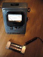
Magnetic field strength
Hello again,
from a friend I borrowed a gaussmeter which measures the strength of magnetic fields with a probe small enough to be positioned in the gap of my ribbon speakers. Here are my findings: Fortunately the field is
a) highly concentrated in the gap
b) linear across the length of the gap; linear part begins after half of first magnet block (some 10 mm) so that total homogeneous field ist just one neodym block shorter than magnet row (9 out of 10)
c) as far as the old gauge is correct field is strong at some 0,5 Tesla (5000 Gauss) in the middle of a 12 mm wide gap between double rows of magnets - see foto.
By the way: I also tested if the field is influenced by the addition of iron pieces across the ends of the frame to close the magnetic flux in the rear of the ribbon. Varnhagen seems to be right in his finding that this doesn't make much of a difference in efficiency - I could hardly see a deflection of the meter pin.
Attachments
I read the book and I took a look at different projects in the internet.
I have a question:
Do you think a longer ribbon made out of 3-5 smaller ribbons makes a difference?
Do you use a 2way or 3way with your ribbon?
I have a question:
Do you think a longer ribbon made out of 3-5 smaller ribbons makes a difference?
Do you use a 2way or 3way with your ribbon?
Re: Magnetic field strength
Ribbon looks good!
Is the result similar to simulation in Femm? I can't get gaussmeter so i need correct simulaton results.
Thanks
MichaelGaedtke said:Hello again,
from a friend I borrowed a gaussmeter which measures the strength of magnetic fields with a probe small enough to be positioned in the gap of my ribbon speakers. Here are my findings: Fortunately the field is
a) highly concentrated in the gap
b) linear across the length of the gap; linear part begins after half of first magnet block (some 10 mm) so that total homogeneous field ist just one neodym block shorter than magnet row (9 out of 10)
c) as far as the old gauge is correct field is strong at some 0,5 Tesla (5000 Gauss) in the middle of a 12 mm wide gap between double rows of magnets - see foto.
By the way: I also tested if the field is influenced by the addition of iron pieces across the ends of the frame to close the magnetic flux in the rear of the ribbon. Varnhagen seems to be right in his finding that this doesn't make much of a difference in efficiency - I could hardly see a deflection of the meter pin.
Ribbon looks good!
Is the result similar to simulation in Femm? I can't get gaussmeter so i need correct simulaton results.
Thanks
FEMM vs. Measurement
Sorry, but I didn't simulate the ribbons so I can't say if measurement correlates well with FEMM-Findings.
Sorry, but I didn't simulate the ribbons so I can't say if measurement correlates well with FEMM-Findings.
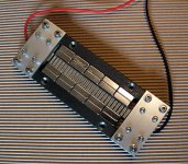
Michael - your gaussmeter tests are very interesting, especially the crossbar results. How big (cross section) was the steel crossbar? Are the plates that you have at the top and bottom of your ribbon made of aluminum?
Denis
Denis
Crossbars
Yes, the plates are made from aluminium. Crossbars were same material as frame of ribbon, i.e. 12x12 mm^2. Measured difference in field strength was really nil.
Yes, the plates are made from aluminium. Crossbars were same material as frame of ribbon, i.e. 12x12 mm^2. Measured difference in field strength was really nil.
Thought of sharing a picture of my first ribbon mid/tweeter that i just got finished.
Magnets i'm using are normal ferrits that i've had laying around for a couple years now, about time they got use 🙂
The next version will probably get some changes in ribbon hook-up and the metal structure at the ends, also have some other ribbons i want to try out. Effective ribbon size is approximately 2,5cmx100cm
Attachments
Something new
Only some findings concerning my experimental transformer at this time: have a look at my homepage at www.michaelgaedtke.de/ribbon_3.htm.
Only some findings concerning my experimental transformer at this time: have a look at my homepage at www.michaelgaedtke.de/ribbon_3.htm.
I'am glad to see new ribbons.
I have finally bought yesterday ndfeb 45 magnets (the strongest type, 30x10x5mm), 50 of them for 50 euros. I think that's excellent price. These 50 are just for one ribbon, i want to hear if it's going to sound good and then make another one. Today i have to buy (or probably get for free if they still have it) mylar, which was used for capacitors but the factory closed capacitor production. I'am hoping to build ribbon soon.
And, one guy wanted specific type of ndfeb magnets for ribbons. He simulated that in maxwell program and said it is the best design. With that shape he gets better field (more uniform). Anyway here is the picture.
Attachments

dhenryp, the chances of me actually making a ribbon myself are quite low but I found your posts fascinating - I love to see things start from a bit of physics and end with measurements of prototypes. More power to your elbow!
EC8010 said:dhenryp, the chances of me actually making a ribbon myself are quite low but I found your posts fascinating - I love to see things start from a bit of physics and end with measurements of prototypes. More power to your elbow!
My elbow thanks you. In fact, in celebration of your complement, I'm going down to the pub and exercise it. 🙂
- Home
- Loudspeakers
- Planars & Exotics
- Another DIY Ribbon thread