Thanks Dhenryp. I use 3DS Max 7. I wanted to make 3d shape out of Femm data, and after thinking about it, it would look funny and you couldn't see anything. This looks more interesting.
And for that crossbars. I was reading your project from beggining (thanks for motivating me!) and as i saw you have all frame made out of metal with magnets inserted there. When i made model in femm i lost field strength but magnetic field was more uniform. Am i making a mistake somewhere?
And if you put magnets close to each other, do they want to move away one from another? And how strong is that force if they do?
I did that calculation wrong, i am sorry for stupid question. I accidently put non magnetic stainless stell instead of magnetic one for crossbars and the results were all wrong. (offcourse). 
In the meantime i got my magnets. I borrowed them for experimenting. They are neodymium type, 30mm x 5mm x 10mm, 6 of them. They are giving me 0.4 Tesla in simulation with crossbars around them. I also have mylar foil, and all i need to do is to find some glue for assembling ribbons and experiment with that.
Big problem i have with my first ribbon speaker, which is going to be a little smaller than Dhendryp's first one, with ribbon around 20 mm wide. I need to have 4 ohm but i can't do that on ribbon below 1m of lenght.(need 5m of 2mm wide alu strips, with 5 of them). So probably i am going to build full 1m lenght ribbon to avoid transformer problems. I have some ideas for puting magnets in the frame without using any glue, but later about that... For now i have all materials for free 😉 , but probably not for long.
I hope that I will have working 1m model before new year. I'll keep posting.
Thanks Denis. Question for you
I wanted to get some idea how this stuff sounds so i put magnets on frame (plastic) to hold them and made simple ribbon from alu foil (like yours). It sounds ok (efficiency is low offcourse), but i noticed two problems. First is that vertical angle where the sweet spot is, is very small - do you have that problem on your construction?. And when someone sings 's' and 'sh' speaker looses detail image - is this problem of distortion and bad positioning of magnets(without steel and crossbars)?
Thanks for answers!
Hi Mx,
The limited vertical dispersion can be a "feature" of tweeter which has a significant vertical length. It could be considered an advantage in that is limits reflections off the floor and ceiling.
I'm not so sure about the problem with "s" and "sh". I don't hear the problem with my speakers. It could be any of the issue you describe. It's also possible that listening to a tweeter by itself, especially one that probably does not go very low, makes it seem that the highest frequencies are exaggerated. One thing you need to be sure of is that the ribbon is not rubbing against the magnets.
Thanks Denis.
Anyway this model i asked you about, is not rubbing surface of the magnets, and i crossed it at 10kHz (sings with full range speaker). And the membrane is travelling a long way if i just turn the volume up a little, even with just very high frequencies that the speaker is doing (active crossover with live! soundcard). And that problem with "s" and "sh" is maybe related to amplifier wich is pumping max power (20w) and i had to even boost soundcard power to +20db (if 0db is standard max output), so maybe there is "some" distortion 😀 .
In simulation i have just 0.1 Tesla with this arrangement, so i have to build a steel frame (with him it would be ~0.4 Tesla), how to calculate how much db at what power is that?
In a few days there will be a steel frame.
Hi MX - I think the fact that the foil is moving a long way at very high frequencies is a clue - if I cross my drivers at ~1.5k the ribbons move a very small amount even at ear splitting levels. The only time I get extreme excursion is when I feed it low frequencies (<500hz). What kind of crossover do you have? If it is active, I would put a capacitor in series with the ribbon. 5-10uf should be large enough to not affect 10k crossover but it will filter out any very low frequencies that are getting through. Your ribbon will respond down to DC (just not very efficiently). If you have a passive crossover, did you take into account that your test ribbon has a very low resistance (probably on the order of 0.1 ohms or less)?
Regarding efficiency, there is a formula early on in this thread that somebody (linesource?) posted that allows you to calculate efficiency. Based on my experience, you should be able to get into the mid-high 80's db with a single small ribbon at .4 tesla. Low to mid 90's with a long one. You still need to come up with a way to deal with low impedance in order to deliver electrical power efficiently to the ribbon. You either have to get the resistance up with a long thin ribbon, come up with an amplifier that is comfortable at very low resistance (<<1.0 ohm), or use a transformer. until you solve this problem it will be very hard to take advantage of whatever efficiency you have.
Regarding efficiency, there is a formula early on in this thread that somebody (linesource?) posted that allows you to calculate efficiency. Based on my experience, you should be able to get into the mid-high 80's db with a single small ribbon at .4 tesla. Low to mid 90's with a long one. You still need to come up with a way to deal with low impedance in order to deliver electrical power efficiently to the ribbon. You either have to get the resistance up with a long thin ribbon, come up with an amplifier that is comfortable at very low resistance (<<1.0 ohm), or use a transformer. until you solve this problem it will be very hard to take advantage of whatever efficiency you have.
I agree with you. Crossover is as i sad active (on live sondcard with kx drivers), but something of low frequencies is escaping to output. I was also thinking about capacitor, will put it.
Yes, Linesource gave the formula. I will make some program to calculate that stuff faster (to compare results), i am very interested in proportion between wider arrangement of magnets and wider ribbon (smaller field, bigger surface of membrane) or the other way-what is more efficient?
And i was thinking about using few crossbars at the back of ribbon (like yours long one Denis), just i will have one long ribbon. I never saw that design in commercial products, but it doesn't make much difference.
And i need 3d program for simulating magnetic field. I found some Magnum which costs 4000$, and some Amperes which offers demo but they didn't send me. Is there any other program for that?
If I remember correctly, the output varies at a rate that is the square of the surface area and also at a rate which is the square of the magnetic strength. On the other hand, magnetic strength decreases at the square of the distance between the magnets.
I've used nothing but the 2-d femm so I can't help you with a less expensive 3d modeler. I found femm adequate for this purpose. In my design, I wanted as few crossbars as possible while still not saturating the poles or crossbars. My design worked out OK but I probably could have increased field strength a little by using thicker material.
I've seen on the forum were people get sucked into a field strength race - "anything under 1 tesla is wimpy". Field strength only affect efficiency and going from .5 to 1 tesla "only" adds 6db. In my case I have ~.5 tesla and the resulting efficiency (coincidentally) almost exactly matches the efficiency of my mid-base line array. If I had quadrupled the cost to double the efficiency (and that is about what it would have cost) I could have gotten 6db more efficiency. In my case, I then would have had to pad down my tweeter to match my mid-base efficiency.🙄
Thanks Denis, you are really helping me with this!
I made a simple dos based program which calculates Spl of ribbon speaker made of mylar and alu foil. It asks you for dimensions of ribbon, desired resistance and magnetic field strenght, and then it writes few options for making ribbon. For example on 1x0.02m ribbon with desired 4Ohm resistance you have options to build 2 narrow alu strips or up to 5 wider and to have the same resistance. (they are connected in serial connection). If stripes are smaller than 1mm they don't appear. Also there is calculated space of at least 1mm beetwen alu stripes. You can compare mass of different ribbons and Spl.
I used thicknesses of materials from that excellent Dahlberg audio design site, formulas that Linesource (sensitivity formula is giving me bad results-where am i making a mistake?) gave us and properties of materials from web.
If there is some bad result coming out, please tell me to fix it. Thanks.
Program is zipped.
Attachments
They are certainly strong enough but all the ones that I've seen are curved. The curve makes it just about impossible to get an equally distributed magnetic field along the length of the ribbon.
Not only they are curved, their direction of magnetization is in different position, so if you make a ribbon with them, it will turn around it's center .
I tried mylar with 10um but it is too thick, you can't coagurate that ribbon, it will be straight in few moments. 2um mylar seems to work nice, only problem is that i don't have it, so i opened one capacitor and found foil inside. It reduces spl by few decibels but it makes ribbon much harder to brake or damage. Now i only have to found capacitors with wide and long enough foil inside them.
I tried mylar with 10um but it is too thick, you can't coagurate that ribbon, it will be straight in few moments. 2um mylar seems to work nice, only problem is that i don't have it, so i opened one capacitor and found foil inside. It reduces spl by few decibels but it makes ribbon much harder to brake or damage. Now i only have to found capacitors with wide and long enough foil inside them.
In what direction HDD magnets are magnetized ? What direction is required for a ribbon ?
I am interested in making a ribbon , but cannot find baisic information , like required magnet direction. Maybe somebody has a good link ?
Bazukaz
I am interested in making a ribbon , but cannot find baisic information , like required magnet direction. Maybe somebody has a good link ?
Bazukaz
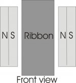
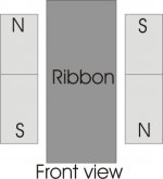
Bellow are pictures (simle sketches). You need direction of magnetization that is normal to electricity flow in ribbon. Also you need magnets that want to get closer to each other (N-S, not S-S or N-N orientation). And whole ribbon needs to have N at one side or S at the other. There are some other arrangements of magnets but this is standard.
First picture shows how it should be done, and the other one how it would be if you put magnets from hard drive).
First picture shows how it should be done, and the other one how it would be if you put magnets from hard drive).
Attachments
Next weekend i am going to audio show which will take place in hyatt hotel in my city. Last time i saw there some excellent riibons which were 2m tall with curved glass behind them, looked beautifull and sounded just like that, only problem was the price ~100.000 euro. Hope that this time will be some more good looking ribbons to look at and take some design ideas 😀 .
Here is improved version of that ribbon calculator i made previously. In this version you can now calculate Spl for aluminium and mylar with aluminium ribbons. You can choose default thicknesses or enter your own.
I hope that i will get some feedback this time.
Thanks
Here is improved version of that ribbon calculator i made previously. In this version you can now calculate Spl for aluminium and mylar with aluminium ribbons. You can choose default thicknesses or enter your own.
I hope that i will get some feedback this time.
Thanks
Attachments
3 micron Aluminum foil?
Believe that somebody posted where to get some 3 micron Aluminum foil some time back. Can anyone tell me where? Thanks for the help. Best regards Moray James.
Believe that somebody posted where to get some 3 micron Aluminum foil some time back. Can anyone tell me where? Thanks for the help. Best regards Moray James.
Denis, can you explain to me what type of transformer do i need if i am going to build pure aluminium ribbon. I am not familiar with audio transformers. If i am going to build short ribbon tweeter, what transformer should i buy and can i build it myself?
Only thing that i understand is that i need 4-8 Ohm on one side of transformer. Does other side need to be with smaller resistance than the resistance of alu. foil? And what type of transformer core do i need?
Thanks
Only thing that i understand is that i need 4-8 Ohm on one side of transformer. Does other side need to be with smaller resistance than the resistance of alu. foil? And what type of transformer core do i need?
Thanks
- Home
- Loudspeakers
- Planars & Exotics
- Another DIY Ribbon thread