Hi Mx - I certainly can help you build a transformer. I built mine and described it earlier and this thread. You can also take look at my web page, where I summarize it and edit out the mistakes:
http://home.comcast.net/~hendentures/index_files/Page331.htm
Best Wishes,
Denis
http://home.comcast.net/~hendentures/index_files/Page331.htm
Best Wishes,
Denis
Cant we just use a current output amplifier - ribbon is perfectly siuted for this - its impedance is flat as a table, damping is not a problem too (air damps ribbon very well) ? Maybe someone tried it ?
I don't think a current source amplifier will help you deal with the high current needed to drive a ribbon. The "naked" ribbon's impedance is so low, that it takes currents on the order of 20 or 30 amps to transfer a significant amount of power to the driver (P=I**2/R). As I understand constant current source amplifiers, they aren't necessarily designed for currents higher than a typical constant voltage amplifier.
Hi Denis,
I disagree and I have built a transconductance amp to experiment with. See the passdiy site for some good white papers on this topic. By the way I think you meant P = I**2 x R.
Graeme
I disagree and I have built a transconductance amp to experiment with. See the passdiy site for some good white papers on this topic. By the way I think you meant P = I**2 x R.
Graeme
gl said:Hi Denis,
I disagree and I have built a transconductance amp to experiment with. See the passdiy site for some good white papers on this topic. By the way I think you meant P = I**2 x R.
Graeme
Hi Graeme,
I looked at the passdiy and I didn't see anything directly related to driving ribbons with current source amplifiers except in the introduction to his full range driver with current source article. If i missed something else, please point me to it.
I would also be very interested to hear more about your amplifier. I've not tried a current source amplifier so I will defer to your experience on the topic.
You're right, of course, about the power formula. It is :
P = I**2 x R
Rearranging to calculate current, you get (if I don't publicly humiliate myself with another 8th grade algebra mistake) is:
I = SQRT(P/R)
My thought process goes like this:
Assuming zero resistance connections, to get 10 watts to the ribbon (a modest power) you need:
I = SQRT(10/.1) = SQRT (100) = 10 amps
When you consider that losses in cables and connectors could easily equal the ribbon resistance, you would lose half your power before it gets to the ribbon, regardless of the type of amp.
The point I was trying to make to VEC7OR was that driving ribbons effectively, with significant power (say 20-30 watts), is not a simple task for either type of amplifier. Also, 99.99% of commercial and DIY amplifiers can't handle it. I think it comes down to choice of what you want to design; a transformer or an amplifier.
Best Regards,
Denis
Hi Denis,
I do agree with most of what you say.
I recommended the passdiy site because Nelson Pass has done a lot of experimentation recently with transconductance amps and the subject of driving ribbons has come up in that context. He had stated that he was going to do some ribbon tests but hasn't done so yet. I have pinged him a time or two on the subject. He's a busy man with lots of other projects.
The bottom line here is that no one to my knowledge has done any serious experimenting with transconductance amps and direct drive of ribbons.
If you want to see the amp I've built. search the passlabs forum for "SOZ Transconductance". There's a picture in post #1 and the final schematic in the last post. Output is about 6-7 watts.
I will use this to drive a 64" ribbon that's .25" wide and 5 microns thick so we're talking 2 - 3 ohms. That changes the results of your calculation. Wish me luck.
Graeme
My first DIY ribbon
I assembled my first DIY ribbon last month - have a look at "Lautsprecher" at http://www.michaelgaedtke.de/ if you're interested in some pictures.
I assembled my first DIY ribbon last month - have a look at "Lautsprecher" at http://www.michaelgaedtke.de/ if you're interested in some pictures.
Hi Michael,
VERY nicely done! I especially like the mechanical design aspect of the top and bottom cross bars and ribbon attachments. The whole thing looks very professional. I do have one personal question (just between you and me 😉 ) - How many taps did you break off threading the pole pieces? I broke quite a few but, for some reason, never remembered to take a picture of it for my web site.
How are you driving them - direct drive or transformer? How do they sound? Come on - share ALL the details!
Once again, great work!
Denis
Direct drive
Hello Denis,
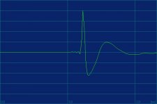
I constructed a small transconductance amplifier - feedback is taken from a small resistance between ribbon and ground so that I get a voltage driven current source. I'm experimenting with a small toroid transformer but results aren't satisfying yet. Sound is very open (I use the ribbon as a dipole). I measured the step response of the prototype (1 kHz aktive Linkwitz-Riley HP , 4th order for safety reasons).
Hello Denis,
I constructed a small transconductance amplifier - feedback is taken from a small resistance between ribbon and ground so that I get a voltage driven current source. I'm experimenting with a small toroid transformer but results aren't satisfying yet. Sound is very open (I use the ribbon as a dipole). I measured the step response of the prototype (1 kHz aktive Linkwitz-Riley HP , 4th order for safety reasons).
Attachments
Ribbon SPL Equations per Verhagen
Hi!
Forgive a change in direction to the thread, but I have been working on mathematical models for calculating SPL for ribbons based on the equations provided by Justus Verhagen in his book. I entered all of his equations into Mathcad to test my model but cannot duplicate his result. Mr. Verhagen claims that using his equations and the data provided that the SPL should be 70dB at 658 Hz. I get 3.056 dB.
I get the same results using either the Mobility or the Impedance Analog.
My Mobility model looks like this (with minor variations due to ASCII text, I used ; as a comment separator):
B := 0.16 ; Flux density
l := 0.045 ; length in m
w := 0.0042 ; width in m
Rc := 0.019 ; ohms
Mmd := 7.649*10^-6; mass
r: = 1 ; listening distance in m
c: = 344; velocity of sound in m/s
P0 := 2.0*10^-5; reference pressure
p0 := 1.18; Air density in kg/m^3
f := 658; frequency
Sd := l*w
k := 2*pi*f/c; =12.018
e := sqrt(Rc); = 0.138 Volts at 1W
Rmr := Sd*p0*c*0.004; using Table data from Bank & Wright
Xmr := Sd*p0*c*0.058; " " "
Raf := Rmr/Sd^2; = 8.591*10^3
Xaf := Xmr/Sd^2
Xaf := Sqrt(Raf^2+Xaf^2); = 1.249*10^5
Zaf := Raf + jXaf
Zab := Zaf; dipole, front = back
Ztotal := (B*l*Rc/Sd^2)+j(2*pi*f*Mmd/Sd^2) + Zaf + Zab
G := e*B*l/Rc*Sd; = 276.372
U := G/Ztotal; = 3.691*10^-6 - j2.434*10^-4
P := U*p0*c*k/s*pi*r; = 2.866*10^-3 - j0.189
SPL := log(P/P0,20); = 3.056 - j0.519 ...but 70 dB expected
The Mobility and Impedance analogs share the same equations for calculations up to Zaf, so, since I get the same answer for either approach the problem is probably before that point.
To get this far I have had to relearn to calculate impedance from 30 years ago. I have finally reached the point where its time to ask for help.
Can any of you tell where I have gone wrong?
Thanks in advance,
Gustava
Hello Gustava,
probably your last line is wrong: I suppose, that
SPL := log(P/P0,20)
should be
SPL := 20*log(P/Po) with Po = 1e-5
Did you try that? You should change your imaginary parts to real numbers. Good luck!
probably your last line is wrong: I suppose, that
SPL := log(P/P0,20)
should be
SPL := 20*log(P/Po) with Po = 1e-5
Did you try that? You should change your imaginary parts to real numbers. Good luck!
Hi Michael,
Changing the last line brought me up to 46 dB --a major improvement! I mistakenly read that line as log20(P/P0) instead of 20log(P/P0).
I'll try fiddling with the imaginary numbers as real to see if I can recover the rest of the 70 dB.
Thanks!
BTW, has anyone tried to replace the table of fixed resistance and reactance from Bank & Wright in Verhagen's book with the corrected equations from JAS "On the Acoustic Impedance of Strip Radiators" S. Lipshitz, et al?
The paper includes a graph lookup for resistance and reactance based on ka that would be more accurate and also simply the SPL equations.
Hello Gustava,
as I checked yesterday evening, Varnhagen took the absolute value (in german from Northrhine-Westfalia to Mecklenburg: den Betrag) of pressure P in his formula.
Good luck!
as I checked yesterday evening, Varnhagen took the absolute value (in german from Northrhine-Westfalia to Mecklenburg: den Betrag) of pressure P in his formula.
Good luck!
Hey
I`ve followed this tread with a large talk about those wonderfull diy ribbons for a long time, and would like to supply.
I`m in the planing phase of building a big line source system, with effective ribbon length 165cm.
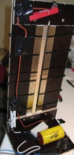
In the weekend I`ve made at little eksperiment, as you can see on the picture. It shows the back af the ribbons!
-2 pcs. N40 i each side (4 in each side), fastnet with plastic strips!
-Pure 11my, 13mm (Width), 30cm (High) aluminiumfoil as membran,
fastnet with Gaffatape.
-Serie capacitor (1khz/6db-oct) and -resistor (1,3ohm)
This work well with my low ohm killer amps 🙂
It sound wonderfull, and better than my old dometweeters 🙂
But also a little "thin" and "touchy?", but this can well be my filter.
When I changed the serie resistor to a 3m long, 1.0cm (width) cut out alufoil, the same materiel as the membran, it made the sound more detailed and delicate 🙂
But to my questions:
How do you construkt your magnet system?
a: The magnet on to each other (flat to flat), like my little eksperiment?
b: Attach the magnets to a piece of iron, and then let this magnified piece of iron do the field
c: What about those ironpcs. acros the back of the magnetics.
I don`t like serie restors, but don`t know about transformers. Haven`t heard them yet....
I planed to use 2, length (170cm) of 10mm width, thin alufoils glued to a mylarfoil, witch shold give me a resistans of about 1,5 - 2,0 ohm, this should do well.
The ribbons should work from ~400hz - 20.000hz, with a area at 2cm width and 165cm high. The baffel should be about 18cm width.
But I like my new pure eksperiment ribbons, and they are much easyer to make than compound 🙂
Cheers Jan Jensen, Denmark
I`ve followed this tread with a large talk about those wonderfull diy ribbons for a long time, and would like to supply.
I`m in the planing phase of building a big line source system, with effective ribbon length 165cm.
In the weekend I`ve made at little eksperiment, as you can see on the picture. It shows the back af the ribbons!
-2 pcs. N40 i each side (4 in each side), fastnet with plastic strips!
-Pure 11my, 13mm (Width), 30cm (High) aluminiumfoil as membran,
fastnet with Gaffatape.
-Serie capacitor (1khz/6db-oct) and -resistor (1,3ohm)
This work well with my low ohm killer amps 🙂
It sound wonderfull, and better than my old dometweeters 🙂
But also a little "thin" and "touchy?", but this can well be my filter.
When I changed the serie resistor to a 3m long, 1.0cm (width) cut out alufoil, the same materiel as the membran, it made the sound more detailed and delicate 🙂
But to my questions:
How do you construkt your magnet system?
a: The magnet on to each other (flat to flat), like my little eksperiment?
b: Attach the magnets to a piece of iron, and then let this magnified piece of iron do the field
c: What about those ironpcs. acros the back of the magnetics.
I don`t like serie restors, but don`t know about transformers. Haven`t heard them yet....
I planed to use 2, length (170cm) of 10mm width, thin alufoils glued to a mylarfoil, witch shold give me a resistans of about 1,5 - 2,0 ohm, this should do well.
The ribbons should work from ~400hz - 20.000hz, with a area at 2cm width and 165cm high. The baffel should be about 18cm width.
But I like my new pure eksperiment ribbons, and they are much easyer to make than compound 🙂
Cheers Jan Jensen, Denmark
Attachments
That looks very nice, especially since you only consider it a prototype! Read through some of the earlier posts or take a look at my website to see how I constructed my ribbon:
http://home.comcast.net/~hendentures/
A quick summary is that I placed the magnets flat on each side of the ribbon. The magnets are attached to steel bra pole pieces with steel cross pieces.
Good luck and keep us all informed!
Denis
http://home.comcast.net/~hendentures/
A quick summary is that I placed the magnets flat on each side of the ribbon. The magnets are attached to steel bra pole pieces with steel cross pieces.
Good luck and keep us all informed!
Denis
Hello Jan,
your ribbon looks very promising indeed! For your questions please have a look at my homepage under "Lautsprecher" where I explained how I constructed my ribbon prototype:
http://www.michaelgaedtke.de
The magnets are glued 'flat to flat' as you put it to two rods of iron 12 by 12 mm squared. Up to now I don't let iron magnify the magnetic field; I left that for further experiments. I too experimented with iron pieces across the structure to close the field at the back, but that doesn't seems to make a big difference in performance so I left them out at the present model.
Hope this will help you. Good luck!
Thanks,
Dennis and Michael, I`ve studied your homepage a lot of times, and find good construktions tips 🙂
I`m just confused of choose the magnet layout. At first I`ve thought of doing it the Dahlberg way like this:
http://www.dahlbergaudiodesign.se/engelska/del1.htm
With to rows of magnetics side by side, but thinking it`s a litle waste of field. The ribbon don`t take large movements, or are ideed not intend to!
By arranged the magnets on to each other, I`ve get at lot stronger field for the same money 🙂
Another way to do the field is described here (The bottom of the side):
http://www.soundimage.dk/Different-col/Ribbon-DIY.htm
This can be made of a masiv iron piece, with cut of corners to hold the 2 magnets (1cm x 1 cm)
Seen something like that on this side (bottom again):
http://www.soundimage.dk/Friends/Andre.htm
Andrè have made a very interesting ribbon her, that is "talked about" in this tread on the danish hifi4all.dk forum:
http://www.hifi4all.dk/forum/forum_posts.asp?TID=9852&PN=1&TPN=15
It`s in danish, but I can translate if you like.
Have a nice weekend 🙂
Cheers Jan Jensen
DIY Ribbon Part I
Here comes the missing part I of my DIY Ribbon article - look at "Ribbon I" under "Lautsprecher" at http://www.michaelgaedtke.de/.
Here comes the missing part I of my DIY Ribbon article - look at "Ribbon I" under "Lautsprecher" at http://www.michaelgaedtke.de/.
- Home
- Loudspeakers
- Planars & Exotics
- Another DIY Ribbon thread