
I've adjusted the currents to 8ma...unfortunately it did not show any progress..It seems that the initial current of the voltage amplifier driver is not enough.
5mA is not enough.
.
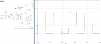
Nice looking square waves..👍 I suppose the numbers to the right of the graph that starts with 346.XXX is the phase...🤔this is what a meander and a Bode diagram look like.
this is the frequency, see attachmentI suppose the numbers to the right of the graph that starts with 346.XXX is the phase...
Attachments
because the main gain in the input stageNice looking square waves..
Great!If you really want Shiklai in the input stage, ultra-linear gain and progressive correction, please ...
see Attachment.
Henk.
Now you only need a PJFET as bootstrap for the Siklai input to make the best LTMD input. 😉
(or BJT with needed accesories, as the Ampslab C200 Siklai LTMD)
Cheers,
M.
Thanks!Great!
By installing a jfet there, the thermal stability of the operating points of the circuit will deteriorate by about 20 times; to stabilize it, you will have to install a servo integrator. If you do not understand what I am writing about, then you can familiarize yourself with the FURY diagrams.Now you only need a PJFET as bootstrap for the Siklai input to make the best LTMD input. 😉
(or BJT with needed accesories, as the Ampslab C200 Siklai LTMD)
I do not recommend using a jfet in circuits without additional stabilization ...
Now that is kind of fast..I wonder if the cfp output can keep up with that speed.
..the slew rate I mean.
..the slew rate I mean.
I actually simmed this one..Ampslab offers a few interesting design for DIY.the Ampslab C200 Siklai LTMD)
Cheers,
M.
Have you also seen the CFP output labeled 'Ultra Linear Design' from Silicon Chip? It uses a cascoded VAS.
Regards,
Albert
why not? CFP is very fast.Now that is kind of fast..I wonder if the cfp output can keep up with that speed.
..the slew rate I mean.
"Ultra linear" is only the first level of quality, much more interesting are "Super linear" ones with a NFB of at least 60 dB and "TOP linear" (HiEND) ones with a depth of more than 90 dB....Have you also seen the CFP output labeled 'Ultra Linear Design' from Silicon Chip? It uses a cascoded VAS.
I simulated and/or build several versions of that AMpslab C200Siklai. One normal, then with LTMD input, which sounds better and then, bootstrapped drivers for the output CFP and later also with cascoded VAS, but I ran out of copper to build the later...I do not want to hijack your thread...I actually simmed this one..Ampslab offers a few interesting design for DIY.
Have you also seen the CFP output labeled 'Ultra Linear Design' from Silicon Chip? It uses a cascoded VAS.
Regards,
Albert
Cheers,
M.
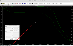
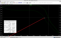
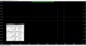
Time for some lesson, 🙂 I am trying to read the nfb depth in LTSpice bode plot. I just do not know if I am doing this right. 1 and 2 cursor data is shown in the small window. I will reflect here what the number reads at the arrow point.
Image one, x=21.483KHz y=28.877dB, 182.795°
Image two, x=5.205MHz y=28.979dB, 183.319°
Albert
Image one, x=21.483KHz y=28.877dB, 182.795°
Image two, x=5.205MHz y=28.979dB, 183.319°
Albert
Attachments
I simulated and/or build several versions of that AMpslab C200Siklai. One normal, then with LTMD input, which sounds better and then, bootstrapped drivers for the output CFP and later also with cascoded VAS, but I ran out of copper to build the later...I do not want to hijack your thread...
Cheers,
M.
👍 It is OK M, we are speaking of CFP's.
Cheers,
Albert
Member
Joined 2009
Paid Member
I can not explain it but I did not like the sound of my TGM2 as much as I would have expected and I attribute this to the use of CFP in the input (an LTP input stage). Compared with the simpler LTP input of TGM1 it had more clarity and impactful bass but it was too harsh sounding for my taste. And it is a matter of taste, so you may have to try it for yourself.
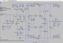
If one, wanted to check on my Singleton.asc files, here it is. LTSpice will report errors and or unrecognized parameters in the log, this is due to the square wave vsource when not in use. You can simply delete the source, but I do think the errors in the log does not affect the results
I now simplified the input removing the other transistor, it now uses only twin pole compensation at VAS. (It is H2 dominant by the way so one cannot expect a very low THD numbers).
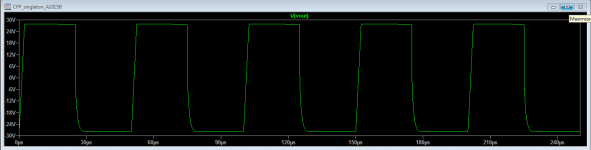
The only obstacle that keeps bothering me was that 'tilted' square waves, I suspect it now lies in the voltages and currents balance.
Albert
I now simplified the input removing the other transistor, it now uses only twin pole compensation at VAS. (It is H2 dominant by the way so one cannot expect a very low THD numbers).
The only obstacle that keeps bothering me was that 'tilted' square waves, I suspect it now lies in the voltages and currents balance.
Albert
Attachments
Last edited:
I am very glad seeing you in the thread.I can not explain it but I did not like the sound of my TGM2 as much as I would have expected and I attribute this to the use of CFP in the input (an LTP input stage). Compared with the simpler LTP input of TGM1 it had more clarity and impactful bass but it was too harsh sounding for my taste. And it is a matter of taste, so you may have to try it for yourself.
Cheers,
Albert


- Home
- Amplifiers
- Solid State
- Another CFP output design attempt.