Sure we can follow tubecad. I have no preference as long as we follow the restrictions as mentioned above. I am not sure if this has been answered, but why C4 on your circuit Koonw? There is already GNFB from C1.
Edit:
I am putting the input on the non-inverting pin following smoking-amps design, not tubecad.
http://www.diyaudio.com/forums/tubes-valves/20686-se-sound-p-p-amplifier.html
Edit:
I am putting the input on the non-inverting pin following smoking-amps design, not tubecad.
http://www.diyaudio.com/forums/tubes-valves/20686-se-sound-p-p-amplifier.html
Sure we can follow tubecad. I have no preference as long as we follow the restrictions as mentioned above. I am not sure if this has been answered, but why C4 on your circuit Koonw? There is already GNFB from C1.
Edit:
I am putting the input on the non-inverting pin following smoking-amps design, not tubecad.
http://www.diyaudio.com/forums/tubes-valves/20686-se-sound-p-p-amplifier.html
I don't think you're referring to anyone, or else I can't see why you don't understand why: it there in the first place, you kick it out.
There is no mention of Global NFB in Tube Cad. I would say it's not a right place, probably no at all or think of better way. We already went through this I believe, that why C4 and behind a reasonable resistor to get rid that hump in your front end. This is to bridge the tube and OpAmp output so to get lowest response.
Last edited:
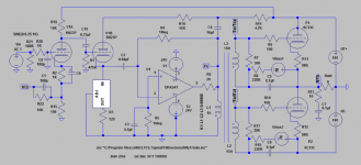
Okay i think i see where the confusion is.
You are referring to this schematic, correct?
Hence, now there is C4 on your circuit since you are translating the op-amp on the tubecad directly to the op-amp on my circuit.
However, on my circuit, i translate the op-amp on tubecad's circuit as the whole amp, starting from the op-amp, interstage transformer and up to the output stage. So, the capacitor (C1) on my amp does not attach to the op-amp output. It attaches way further back to the speaker output of the 6C33C output stage. This means i am enveloping the whole circuit in the negative feedback. Of course this raises question about stability as i asked way back on my first post.
You are referring to this schematic, correct?
An externally hosted image should be here but it was not working when we last tested it.
Hence, now there is C4 on your circuit since you are translating the op-amp on the tubecad directly to the op-amp on my circuit.
However, on my circuit, i translate the op-amp on tubecad's circuit as the whole amp, starting from the op-amp, interstage transformer and up to the output stage. So, the capacitor (C1) on my amp does not attach to the op-amp output. It attaches way further back to the speaker output of the 6C33C output stage. This means i am enveloping the whole circuit in the negative feedback. Of course this raises question about stability as i asked way back on my first post.
The C4 in Koonw's circuit makes just the front end act like the emulation triode. Leaving it out makes the whole amplifier act like the triode, via the global feedback from C1.
Broskie's circuit is using the Op Amp as an I to V converter. While Ballpencil's circuit is using the op amp as a V to V amp. In the Broskie case, the triode is constrained to maintain dVp/dVg as Mu, to maintain constant current to the Op Amp. In Ballpencil's case, the triode provides dVp/Mu at the cathode, which must match the voltage at Vin. So dVin = dVout/Mu. Both giving the same result (if C4 not there), other than the gain restriction on the Op Amp in the Broskie case from the 1 Meg local feedback path to get I to V conversion.
The global Fdbk case does require more attention to phase/stability.
-------------------------
"Nope, the capacitance theory advanced by Smoking Amp is shot down."
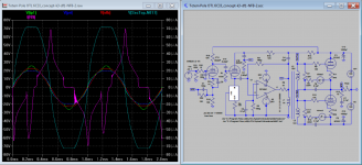
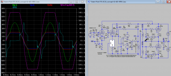
Not quite! See Koonw's results below. The big current spike is obviously grid current. The little current peaks at crossover are from the global feedback making up for the low gm of the tubes at crossover by increasing the drive swing temporarily. This excites the Miller effect temporarily to give the small current peaks.
Broskie's circuit is using the Op Amp as an I to V converter. While Ballpencil's circuit is using the op amp as a V to V amp. In the Broskie case, the triode is constrained to maintain dVp/dVg as Mu, to maintain constant current to the Op Amp. In Ballpencil's case, the triode provides dVp/Mu at the cathode, which must match the voltage at Vin. So dVin = dVout/Mu. Both giving the same result (if C4 not there), other than the gain restriction on the Op Amp in the Broskie case from the 1 Meg local feedback path to get I to V conversion.
The global Fdbk case does require more attention to phase/stability.
-------------------------
"Nope, the capacitance theory advanced by Smoking Amp is shot down."
Not quite! See Koonw's results below. The big current spike is obviously grid current. The little current peaks at crossover are from the global feedback making up for the low gm of the tubes at crossover by increasing the drive swing temporarily. This excites the Miller effect temporarily to give the small current peaks.
Attachments

Last edited:
But the difference is he is bridging to output instead OpAmp, whether this is what he wants I don't know. Now here is my other approach to deal with possible instability caused by global Fdbk and OpAmp bridging. Just shift global Fdbk front, and now you can see what differences it made.
For those still with me can sim to check and open another thread if you wish since this thread is getting too long..I don't find it's easy to add another stage in the original idea and maybe better to use lower mu tube to improve stability - the interstage transformer needs to add internal DCR.
For those still with me can sim to check and open another thread if you wish since this thread is getting too long..I don't find it's easy to add another stage in the original idea and maybe better to use lower mu tube to improve stability - the interstage transformer needs to add internal DCR.
Attachments
Last edited:
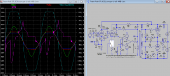
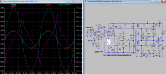
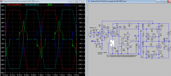
Here are 3 snapshot of my new schematic sharing any discussion.
1) The driver now is constant voltage limiter/ driver.
2) There seen no more significant grid current as driver voltage just barely touch the zero point clipping flat but no further.
3) Why? Already excited? Try to play with sim. it's really quite fun.
Welcome any comment.
1) The driver now is constant voltage limiter/ driver.
2) There seen no more significant grid current as driver voltage just barely touch the zero point clipping flat but no further.
3) Why? Already excited? Try to play with sim. it's really quite fun.
Welcome any comment.
Attachments
Last edited:
Add this to earlier note:
4) Reducing R17 and R27 inductor load resistors from 30K to 20K eliminated the extra grid current spike.
4) Reducing R17 and R27 inductor load resistors from 30K to 20K eliminated the extra grid current spike.
Attachments
Last edited:
May it is time to spin your designs to a new thread, getting confused by the multiple variations...
It is not entirely my design, ideas from many people are incorporated. As far I am concerned I am satisfied with the results. If other issue I can't solve I will open new thread, so do you.
But the difference is he is bridging to output instead OpAmp, whether this is what he wants I don't know.
Yes, this was intentional. As explained by smoking-amp, bridging to the output was an attempt to make the whole circuit emulates the feedback triode, not just the op-amp part.
It's either you bridge just the output or just the op-amp. Not both.
Now here is my other approach to deal with possible instability caused by global Fdbk and OpAmp bridging. Just shift global Fdbk front, and now you can see what differences it made.
Adding another pole removes instability? Can you please explain this?
So, have we finally established that Vgk remains negative for the full cycle?
No. We have established that grid current flows.
Koonw's plots show considerable grid current with only +,-49V drive and an output of about +,-18V. Not full output.
I explained before that your grid capacitors allow grid current to drive the whole grid waveform more negative, charging the capacitors and increaing the bias. So, following a drum thump or large transient, the tunes are parallysed for a short time. That equates to lots of distortion. You need to get rid of those grid capacitors. You need to increase the bias so the tubes are near cut-off. You need to accept that your amp is Class B and make it a good Class B.
Sounds fair. But if you increase the HT to +,-180V there's a big improvement. If you also increase the bias to 70V grid current almost ceases to be an issue.1. +/-150V is chosen with the consideration this is the value we get after rectifying 110+110VAC transformer, with some spare for voltage drop in the mains line. I design my amp so that i can use simple isolation transformer which usually comes with 110VAC secondary tap. This translates to economy.
The servo range into R2 is -36V to -60V. Not really enough.2. The upper tube should be able to be biased with servo and utilize the lower -150v supply with some voltage divider. This avoids having an extra supply just for bias purpose.
Be carefull with this sort of thing.3. The lower tube will also be biased with voltage multiplier from the original 110+110VAC transformer. Again, avoiding extra power supply just for bias purpose.
Grid current (yes, you must accept that there will be grid current) can charge up the supply capacitors and the rectification diodes just stay off and never conduct. Ensure there is an adequate bleeder load.
It is bad practice to drive a transformer direct from an op-amp. Reducing R3 and R4 does not really address this. R3 is ineffective due to paralleling with the signal source.I added 0.5R series resistance (a reasonable value, no?) on The transformer primary (L1) and reduce R3 and R4 to 22k and this simulates to around 0.3mA standing current on the primary.
Last edited:
Yes, this was intentional. As explained by smoking-amp, bridging to the output was an attempt to make the whole circuit emulates the feedback triode, not just the op-amp part.
It's either you bridge just the output or just the op-amp. Not both.
Adding another pole removes instability? Can you please explain this?
You think you can fly before you walk? Of course not both, I am trying to figure that out eve since you post it.
I don't understand your question. You bet you can solve your inter-stage transformer stability while try to apply 100% global NFB while I try isolate it.
If you continue to argue for your own benefit without examine your own behavior first, don't expect me or any one to answer your question.
Last edited:
You think you can fly before you walk? Of course not both, I am trying to figure that out eve since you post it.
I don't understand your question. You bet you can solve your inter-stage transformer stability while try to apply 100% global NFB while I try isolate it.
If you continue to argue for your own benefit without examine your own behavior first, don't expect me or any one to answer your question.
eh? why the offense?
I don't bet i can solve the instability while trying 100% gnfb. I don't even know if it's stable or not. I was asking at the start of this thread to adjust the transformer values to something more reasonable (adjust coupling value, add DC resistance, add winding capacitance) then help me check whether it's stable or not. If it's unstable, i won't lose sleep trying to stabilize it. I will probably ditch the idea and go for the proven inverted Futterman.
I am not being modest when i say i am a newbie. I truly don't know when i ask questions. I know that the least poles you have on the circuit, the better it is for stability, that's why jerluwoo DC couples the transformer secondary to the grid. Now i see you add one more pole. Isn't it logical for me to ask how is this beneficial on reducing the stability?
edit:
Of course not both, I am trying to figure that out eve since you post it.
But you are putting both caps. See smoking-amps' post on #124. You put both caps. This is what i don't understand.
Last edited:
eh? why the offense?
I don't bet i can solve the instability while trying 100% gnfb. I don't even know if it's stable or not. I was asking at the start of this thread to adjust the transformer values to something more reasonable (adjust coupling value, add DC resistance, add winding capacitance) then help me check whether it's stable or not. If it's unstable, i won't lose sleep trying to stabilize it. I will probably ditch the idea and go for the proven inverted Futterman.
I am not being modest when i say i am a newbie. I truly don't know when i ask questions. I know that the least poles you have on the circuit, the better it is for stability, that's why jerluwoo DC couples the transformer secondary to the grid. Now i see you add one more pole. Isn't it logical for me to ask how is this beneficial on reducing the stability?
edit:
But you are putting both caps. See smoking-amps' post on #124. You put both caps. This is what i don't understand.
1) How do you know your amp can work with other amps? What will happen if they bridge with your amp. These are a few questions I will ask myself so do you?
2) The amp stability do not depend entirely on the components, why u only insist that part and not the whole system?
3) Has he built that amp? It has been ten years ago where can I find it?
4) I merely came out with first stable version for people to share whether good or bad, and try extract any useful data by sim. My last version give me even more precise data. Still do these action offended you also? Or else you think you can improve it by sticking to unproven built or what?
Last edited:
eh? why the offense?
I don't bet i can solve the instability while trying 100% gnfb. I don't even know if it's stable or not. I was asking at the start of this thread to adjust the transformer values to something more reasonable (adjust coupling value, add DC resistance, add winding capacitance) then help me check whether it's stable or not. If it's unstable, i won't lose sleep trying to stabilize it. I will probably ditch the idea and go for the proven inverted Futterman.
I am not being modest when i say i am a newbie. I truly don't know when i ask questions. I know that the least poles you have on the circuit, the better it is for stability, that's why jerluwoo DC couples the transformer secondary to the grid. Now i see you add one more pole. Isn't it logical for me to ask how is this beneficial on reducing the stability?
edit:
But you are putting both caps. See smoking-amps' post on #124. You put both caps. This is what i don't understand.
What is all this?
You claim to know the reactance of the transformer windings. You can measure the DC resistance of the windings by passing a known DC current through them and measuring the volt drop with a good DVM. You can easily measure the leakage reactance by the "short all other windings" method. With an oscillator, you can serch for resonance and from that get a rouigh measurement of winding capacities.
Don't have the knowlege to do that? Don't have the test gear? In that case you really are trying to fly without knowing how to walk.
Perhaps i should emphasize again that when i ask questions, i am not challenging. I am simply asking out of curiosity.
With 49Vpp drive and -47v bias, the Vgk will be +2V at the peak of the grid drive. This is why there is grid current, isn't it?
I think the full output on my circuit is determined by when Vgk reaches zero. Not by the op-amp clipping. I am not asking the 6C33C to get more current by driving it with positive grid. Whatever the 6C33C gives me when Vgk =0 (which is 2A as per my model), i am happy to call it full output.
Grid current ceases to be an issue until you drive it with 72Vpp grid drive, doesn't it? At this level of drive, we should be getting the same grid current issue as the 49Vpp drive & 47V bias case.
No. We have established that grid current flows.
Koonw's plots show considerable grid current with only +,-49V drive and an output of about +,-18V. Not full output.
With 49Vpp drive and -47v bias, the Vgk will be +2V at the peak of the grid drive. This is why there is grid current, isn't it?
I think the full output on my circuit is determined by when Vgk reaches zero. Not by the op-amp clipping. I am not asking the 6C33C to get more current by driving it with positive grid. Whatever the 6C33C gives me when Vgk =0 (which is 2A as per my model), i am happy to call it full output.
Sounds fair. But if you increase the HT to +,-180V there's a big improvement. If you also increase the bias to 70V grid current almost ceases to be an issue.
Grid current ceases to be an issue until you drive it with 72Vpp grid drive, doesn't it? At this level of drive, we should be getting the same grid current issue as the 49Vpp drive & 47V bias case.
BallPencil, your amp is unstable because you have a 3rd order LF rolloff with two coincident poles: C3-R2 at 3.28Hz and C1-R1 at approx 3.28 Hz.
But I never mentioned this before because the problem is fixed by the same means as fixing the grid blocking distortion: Get rid of those 220 nF grid capacitors.
But I never mentioned this before because the problem is fixed by the same means as fixing the grid blocking distortion: Get rid of those 220 nF grid capacitors.
"I think the full output on my circuit is determined by when Vgk reaches zero. Not by the op-amp clipping. I am not asking the 6C33C to get more current by driving it with positive grid. Whatever the 6C33C gives me when Vgk =0 (which is 2A as per my model), i am happy to call it full output."
It is the transformer capable to drive and continue to drive above zero, how you can have any control? I have so much data waveform do they all go pass above your head?
It is the transformer capable to drive and continue to drive above zero, how you can have any control? I have so much data waveform do they all go pass above your head?
Last edited:
I think the full output on my circuit is determined by when Vgk reaches zero. Not by the op-amp clipping. I am not asking the 6C33C to get more current by driving it with positive grid. Whatever the 6C33C gives me when Vgk =0 (which is 2A as per my model), i am happy to call it full output.
That is an extremely bad approach.
You can't make a silk purse out of a sow's ear by describing it as silk.
Music is very peaky. Virtually all audio amplifiers are driven occaisonally to clipping during any musical performance. This especillay applies to amplifiers with low power outputs such as yours, even with high efficiency speakers. With a competently designed amplifier, the clipping is clean and there are no recovery artifacts. When this is the case, most people do not detect the occaisonal clipping, and if they do detect it, it doesn't sound unpleasant to them.
But with an amplifier with recovery artifacts, such as yours, the listening impairment becomes obvious.
Last edited:
It is the transformer capable to drive and continue to drive above zero, how you can have any control?
This may sound silly: i can control by reducing the volume control. Is this feasible?
Once i hear the amp distorting (which comes from Vgk being positive), i dial down the volume.
Perhaps i'm being too simple but i imagine it's the same case as a simple gainclone with limited power supply. The chipamp maybe able to supply more current but since it's clipping, i simply dial down the volume until it no longer clips.
- Status
- Not open for further replies.
- Home
- Amplifiers
- Tubes / Valves
- Another Approach to Totem Pole OTL Amplifier