
Datasheet is for multiple models (different voltages).Chech if dc/dc mfr specifies a min or max value.
It says "OUTPUT MAY BE EXTERNALLY TRIMMED (+-13%)"...
But I had missed "Voltage tolerance +-3%, includes set up tolerance"....
This explains everything...
Ok, Well if that wont work, I will get LDO...I think more like 1000uF... Current consumption of tablet is not so small , also diode voltage drop is not constant, but current dependent. So voltage still may look like unstable to tablet , like it was with resistor .
It is 5.00vWhat output your converter outputs with trim pin unconnected ? If it's 5,00V , these 3 percent can be ignored then.
I have another hack idea , how to adjust down converters output voltage , but no implementation yet, without breaking galvanic isolation . Idea is to shift trim pin voltage by lets say +0,2V upper than output voltage. It can be a schottky diode and resistor to +12V simply, no high current needed. But ground must be common then , for diode to operate. This would extend trim range to lower level.
You can test that , by using 10k potentiometer ,any diode, and 47k resistor , but join input and output grounds together.
You can test that , by using 10k potentiometer ,any diode, and 47k resistor , but join input and output grounds together.
Problem with diode is not constant ,also temperature dependent ,forward voltage drop.With low current schottky diode may have even 0,1V , but with several amperes it may reach 0,5V maybe . While standard Si diode varies from 0,5V to 1,3V ... It may be tricky to select matching diode , but luckily we have trim pin .
Perhaps a LM385 plus an opamp and a PMOS will make a good low drop voltage regulator adjustable.
Sounds realistic . Just need to find p-mosfet , which can fully open to few milliohms at less than 5Volts. Probably logical level pmos .Lm358 have its drawbacks , like zero drift , had to replace it to some better to make working solid. Also output voltage is supply voltage - 1,5v , so sensitive mosfet may be unable to fully close. At best , rail-to-rail ic with low drift to be used there.
There are several opamps 3.3 and 5V capable, mainly CMOS that are which I most like. A Logic level PMOS as series pass.
But IMO, with the DC/DC as is, adjusted to minimum and considering loss in cables and connectors, may suffice as is.
But IMO, with the DC/DC as is, adjusted to minimum and considering loss in cables and connectors, may suffice as is.
I agree , it may be ok with load, when tablet is operating and consuming it's 1,5Ampere. But we get no voltage drop on cable, when as op mentioned, it consumes about 60ma in standby , then we get overvoltage.
Have used TLV9102 and it works much better than lm358, also exist single version TLV9101 , but I don't know their current availability.
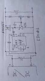
Two ideas about home made LDO.
The #1 uses a charge pump to create twice the DC/DC voltage output to have large enough gate voltage over its source to operate NMOSFET as series pass.
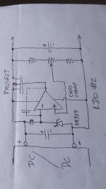
The #2 uses a PMOSFET plus a CMOS OpAmp and a micropower reference. As PMOS needs gate voltage below its source, no need for charge pump.
Obviously each has their pros and cons.
The #1 uses a charge pump to create twice the DC/DC voltage output to have large enough gate voltage over its source to operate NMOSFET as series pass.
The #2 uses a PMOSFET plus a CMOS OpAmp and a micropower reference. As PMOS needs gate voltage below its source, no need for charge pump.
Obviously each has their pros and cons.
Attachments
Hy,
Thank you both for thinkering on LDO situation.
I had just wired the diode & 2200uF cap in series.
Voltage is 4.45v when tablet is completely off and 4.24 - 4.27v when on, 4.31v when in stand by mode (locked screen, no activity).
0 AC on power rails.
I would call it good, would you also (keep in mind my current as small as possible situation)?
I do still get a bit of noise on the audio path... slight hiss before the playback starts and after it stops. This hiss starts and ends with a click.
I needed to remove the ground loop isolator on audio path as there was loud buzz as grounds are not common anymore.
I won't bother you with this as amp in question is cheap class D amp that has common audio gnd and power gnd. This amp will be removed and I must still add the eq (eq has gnds seperated).
However I would like you ask something else... Do you have any knowledge about USB lines?
I forgot that using dc dc converter will also seperate usb hub gnd and tablet gnd. Usb hub is powered by another smps, I disconnected vcc+ and gnd on the USB, only Data+ and Data- are wired from tablet to usb hub.
Voltage between gnd and isolated gnd differs for 0.08v max and usb is working fine.
Should I worry about that?
If this is not ok, I will need to add usb isolation.
EDIT:
If I'm not mistaking, usb uses differential signal, no gnd needed?
Ok, here I have more freedom as I don't need to stay in current limits.
Ground loop isolators with 1:1 trafos seem to "colour the sound", is this also the case with phocoupler?
I would like to execute my plan first (eq, different amp) and go from there.
I believe that this chinesse class D amp is the big problem remaining...
Ground loop isolators with 1:1 trafos seem to "colour the sound", is this also the case with phocoupler?
I would like to execute my plan first (eq, different amp) and go from there.
I believe that this chinesse class D amp is the big problem remaining...
- Home
- Source & Line
- Digital Source
- Android tablet injecting digital noise to power lines