Hi. Interesting problem , as i understand, you have ground loop between audio ground and tablet battery negative pin. I would recommend isolated dc dc converter ,designed for 5v output ,but with potentiometer, to adjust output to 4,2v . Input range as should be 9-18v. Also one benefit , which you will get ,is decreased current consumption from 12v battery. Let's say your tablet needs 60ma from 4,2v in standby, and dc dc converter has efficiency much better than lm317 or similar linear circuits. You have 3 timer higher input voltage than output , i think your current consumption will decrease twice . Lm2596 is not solution ,because its effeciency is low at low voltage difference, because it has bjt inside, not MOSFETs switch. Also not isolated. Also you can try to power tablet from lm2596 from additional small 12v battery , with no connection to car's ground. If you get no noise , then is it , you need isolated galvanically power supply for tablet. Audio isolation transformers i would not recommend, they will add some distortion , and probably reduce low frequencies.

I will get the isolated DC DC converter, but I cant find adjustable isolated one.
If anyone knows of suitable one (at least 2A or 1.5A at 4v, isolated) please let me know.
I can find only with 5v output, but I can't think of another way apart of using LDO regulator after the converter to ge to 4.2v.
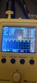
This is the oscillation if I use resistor in series, also if I use a diode. Adding capacitance on the tablet side lowers the frequency, this is the waveform with 100ohm resistor and 7 x 4700uF capacitors.
What could be causing this?
If anyone knows of suitable one (at least 2A or 1.5A at 4v, isolated) please let me know.
I can find only with 5v output, but I can't think of another way apart of using LDO regulator after the converter to ge to 4.2v.
This is the oscillation if I use resistor in series, also if I use a diode. Adding capacitance on the tablet side lowers the frequency, this is the waveform with 100ohm resistor and 7 x 4700uF capacitors.
What could be causing this?
Attachments
Oscillation caused by internal dc dc converters starting and stopping , or changing duty cycle quickly ,inside tablet. Cpu power consumption is not constant, reducing it while idle , changing operating frequency , thus causing these current peaks. If you put resistor in series , voltage will be lower , thus current will increase. With inductor you may a little smooth it , without dc voltage drop. But you can't put it on ground line, because then you will add all the ripple to audio ground wire .
Thank you for explanation. While I understand why resistor would cause this, I still can't understand why a diode would cause the same behavior.Oscillation caused by internal dc dc converters starting and stopping , or changing duty cycle quickly ,inside tablet. Cpu power consumption is not constant, reducing it while idle , changing operating frequency , thus causing these current peaks. If you put resistor in series , voltage will be lower , thus current will increase. With inductor you may a little smooth it , without dc voltage drop. But you can't put it on ground line, because then you will add all the ripple to audio ground wire .
There is the elephant in the room which is the phones battery management IC which is still expecting a lithium battery to be there, not a DC feed. It is at least going to poke the battery. Also note that Lithium Ions are full charged when both conditions are true. The battery is at 4.2V and the charge current has reduced to a minimum limit. So it's still going to check the battery, even though it has no power to charge it.
A lithium battery in a phone can supply bursts of 10s or 100s of amps. It's like a big capacitor.
If you are using a resistor in any circuit where the load changes the voltage will change with it.
A lithium battery in a phone can supply bursts of 10s or 100s of amps. It's like a big capacitor.
If you are using a resistor in any circuit where the load changes the voltage will change with it.
I am about to order Dc Dc converter,
Meanwell SDM30-12S5...
5v 5A
There is a trim pin and datasheet claims that it's output can be adjusted by +-13%, this means that I will be able to set voltage to 4.35v, thats great.
Is there a reason not to use this one for my case, before I order? I think that this one is as good as I will get.
Meanwell SDM30-12S5...
5v 5A
There is a trim pin and datasheet claims that it's output can be adjusted by +-13%, this means that I will be able to set voltage to 4.35v, thats great.
Is there a reason not to use this one for my case, before I order? I think that this one is as good as I will get.
Looks expensive , but it should work . Datasheet specifies efficiency 80 percent , but thats because of low output voltage , probably diode at output ,not SR. Unknown parameter is maximum load capacitance allowed ,but because converter limits output power , it should charge some additional capacitor without problem, if you separate it with inductor.
Manufacturer did nice job putting 25w psu in so small size.
Manufacturer did nice job putting 25w psu in so small size.
It is isolated & regulated, 47 - 100 uF input cap required, no info if output cap is required, I guess it isn't then.Check that it is isolated and regulated. Many of them are unregulated. And verify the need or not for extra output/input capacitances.
Only thing I'm not sure about is what resistor to use for trimming voltage. Datasheet states fixed resistor or pot.

This is all about trimming stated in the datasheet. If I understand correctly, I don't need a resistor at all. I just need to connect TRIM pin directly to -VOUT pin. Based on how use of pot is shown.
Last edited:
According to trim pin connection from picture ,on the right, named down , trim pin should be connected to out+ via small resistor or directly for decreasing voltage. Internal resistor limits adjustment to 13 percent as i understand. You can use small resistor for load like 47 ohms for test , anyway output voltage is regulated, load independent.
Ok, you both confirmed my assumptions.
Will try with low value resistor and see if it is down to -13%.
If I will get too much ripple or voltage won't be low enough, I can still add LDO to the output (I don't like the idea because of additional current, but ok).
I'm doing a research just to understand how such converters work, this is a flyback converter right?
- Home
- Source & Line
- Digital Source
- Android tablet injecting digital noise to power lines