MFB electronics
What a wonderful project Armand !
Being the owner of the dutch MFB project it's both surprising & exiting to find the 537 prototype made it onto the big & almighty diyaudio 🙂 Reading your thread makes me wonder if we could somehow join forces as there seems to be an already strong alignment of our interests in this matter.
To take away any confusion as to what the 537 project is about please allow me a brief introduction, the main reason the 537 project was started is to bring MFB back into production for reasons already described in this thread : clean LF from small enclosures. For starters I build a copy of the original 22AH587 electronics using LM3886 chips. The boards below contain a 3 way substractive x-over, a limiter, feedback correction, feedforward filter, 3ch amps, dc protection and onboard buffers.
These modules were then combined with a connexelectronics smps to form plate amps.
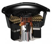
Which got fitted into this prototype, as you can see the woofer is already equipped with a custom made accelerometer. The enclosure in the back is an original 532, Philips first MFB dating 1973.
As you understand one is completely free to choose the mid & hi drivers of their liking and it's noteworthy that this homegrown MFB is actually performing really well using this cheap china woofer, provided you equip them with a accelerometer off course 😀 By the way, we are also experimenting with corrected 15" drivers but as MFB is really all about small & beautifull our focus remains with 8 inch for now.
I'm actually quite curious to learn what your XLS is capable of when hooked up to this module. Next step is to further improve the electronics, making everything fit onto 1 pcb, this here is an eagle3D mockup of the next version where all 0411 resistors have been replaced by 0805 smd and moved to the copperside.
Being based upon 30+ year old electronics we are slowly modernizing the schematics away from discrete bc547/557 designs towards opamps and class d chips for bass amplification.
What a wonderful project Armand !
Being the owner of the dutch MFB project it's both surprising & exiting to find the 537 prototype made it onto the big & almighty diyaudio 🙂 Reading your thread makes me wonder if we could somehow join forces as there seems to be an already strong alignment of our interests in this matter.
To take away any confusion as to what the 537 project is about please allow me a brief introduction, the main reason the 537 project was started is to bring MFB back into production for reasons already described in this thread : clean LF from small enclosures. For starters I build a copy of the original 22AH587 electronics using LM3886 chips. The boards below contain a 3 way substractive x-over, a limiter, feedback correction, feedforward filter, 3ch amps, dc protection and onboard buffers.
An externally hosted image should be here but it was not working when we last tested it.
These modules were then combined with a connexelectronics smps to form plate amps.
An externally hosted image should be here but it was not working when we last tested it.
Which got fitted into this prototype, as you can see the woofer is already equipped with a custom made accelerometer. The enclosure in the back is an original 532, Philips first MFB dating 1973.
An externally hosted image should be here but it was not working when we last tested it.
As you understand one is completely free to choose the mid & hi drivers of their liking and it's noteworthy that this homegrown MFB is actually performing really well using this cheap china woofer, provided you equip them with a accelerometer off course 😀 By the way, we are also experimenting with corrected 15" drivers but as MFB is really all about small & beautifull our focus remains with 8 inch for now.
An externally hosted image should be here but it was not working when we last tested it.
I'm actually quite curious to learn what your XLS is capable of when hooked up to this module. Next step is to further improve the electronics, making everything fit onto 1 pcb, this here is an eagle3D mockup of the next version where all 0411 resistors have been replaced by 0805 smd and moved to the copperside.
An externally hosted image should be here but it was not working when we last tested it.
Being based upon 30+ year old electronics we are slowly modernizing the schematics away from discrete bc547/557 designs towards opamps and class d chips for bass amplification.
Last edited:
Unfortunately many(most?) readily available mics are not capable of handling high SPL at low frequencies without self-generated distortion, so measuring the accelerometer output is the next best thing. I was spoiled by having access to a B&K 4133 mic when doing my testing.
Why fixated on sticking the mic inside the driver? No reason I can see for this research purpose.
Sadly, I am too deficient in physics to be sure, but does the accuracy of the mic have to be of the same order as the sensor device inside the loop?
Anyway, let's get back to tone bursts and pulse responses. If it doesn't sound too heretical (after my criticism of simulations and flexible cones), I doubt the objective assessment of woofer quality can be entirely reflected by frequency runs or a Fourier series of error tones.
Ben
Thank you all for your feedback on my project. I'm back in my dungeon after some nice and warm days and will try to answer some of your questions.
Ben:
Your loop-gain questions in post #6 and #14 are similar to what I also was asking myself when I started this project but I kind of figured out how it worked after some testing. I had potmeters pretty much everywhere in the circuit and it does not matter where you increase the gain as long as you do it inside the loop. I can confirm that Bolserts good explanation (and picture) in post #16 regarding this is correct. The reason I chose R9 and R8 to give a fixed gain of 9.4 is beacuse that makes the accelerometer able to handle g-force up to 144g before clipping.
Square tone bursts as ordered:

Figure 1.

Figure 2.
*Waterfall

Figure 3.

Figure 4.
454Casull:
To lower distortion further, more loop gain will help. I can see better and better THD figures all the way up to where oscillation starts.
CharlieLaub:
I am not sure why 2nd and 3rd are the way they are. I suspect it is just the microphone itself adding the 2nd. The DC offset of the LM3886 is my last worry now. It is very small compared to what I have in my servo circuit. I am considering wrapping a DC servo around the whole circuit.
Bolserst:
*I have now manually measured phase from 0.1Hz to 1kHz (phuu..) I will post the results in a separate post
* Sorry if it was unclear where I fed the input signal. It is indeed fed to R1 with U1 gain set to 1x! (Your red X picture was very informative BTW.) This is because I wanted the possibility of having offset adjustments from the U1 opamp. I have calibrated my soundcard in REW to compensate for the phase and gain error introduced by the R1-C1 LP filter (even if it is at amuch higher frequency).
* Regarding the 2nd harmonic discrepancy between the accelerometer and the microphone I did a test today. Both mics 1-2” from cone. SPL 112dB. With “brand X” mic the 2nd harmonic was 10dB higher than 3rd harmonic. With my mic the 2nd harmonic was only 1.5dB higher than 3rd harmonic. (like in post #3). I therefore suspect that the 2nd harmonic is microphone related. The woofer sits sideways.
* A larger C2 coupling capacitor gives me more DC error. I don’t have any oscillation problems at low frequencies. Only DC build-up problems. We will have to come back to my phase margin situation when I have posted my new phase measurements.
* Yes, the discontinuity at 145Hz is there also with open loop microphone measurement.

Figure 5.

Figure 6.
SuperR:
Sub 20Hz will come in a new post. Is 0.1Hz good enough for you??? 😀
Lehmanhill:
Very nice of you to offer me help with this project. I have read your article so many times I feel like I almost know you 😛
Chriscam:
I read your thread with google translate. Really nice project! I did however not manage to see so much information about the MFB part?? I am more than happy to join forces. 🙂
Ben:
The reason for sticking the mic close to the cone is to reduce the influence of the room. I just did a test now, and moving the mic further away from the cone increases the 2nd harmonic percentage of the fundamental. However, this is not always the case. At very high SPL (117dB) it is the opposite which indicates microphone distortion.
Ben:
Your loop-gain questions in post #6 and #14 are similar to what I also was asking myself when I started this project but I kind of figured out how it worked after some testing. I had potmeters pretty much everywhere in the circuit and it does not matter where you increase the gain as long as you do it inside the loop. I can confirm that Bolserts good explanation (and picture) in post #16 regarding this is correct. The reason I chose R9 and R8 to give a fixed gain of 9.4 is beacuse that makes the accelerometer able to handle g-force up to 144g before clipping.
Square tone bursts as ordered:
Figure 1.
Figure 2.
I don’t understand what this means. Please explain and I'll do the test.Just eyeballing the mic results for a square wave whose freq is chosen to sit inside a "times 10" and "divided by 10" woofing band can be very informative, with and without MF. Guess that's what I'd think is the best picture you could give us, even better than a tone burst*.
*Waterfall
Figure 3.
Figure 4.
454Casull:
To lower distortion further, more loop gain will help. I can see better and better THD figures all the way up to where oscillation starts.
CharlieLaub:
I am not sure why 2nd and 3rd are the way they are. I suspect it is just the microphone itself adding the 2nd. The DC offset of the LM3886 is my last worry now. It is very small compared to what I have in my servo circuit. I am considering wrapping a DC servo around the whole circuit.
Bolserst:
*I have now manually measured phase from 0.1Hz to 1kHz (phuu..) I will post the results in a separate post
* Sorry if it was unclear where I fed the input signal. It is indeed fed to R1 with U1 gain set to 1x! (Your red X picture was very informative BTW.) This is because I wanted the possibility of having offset adjustments from the U1 opamp. I have calibrated my soundcard in REW to compensate for the phase and gain error introduced by the R1-C1 LP filter (even if it is at amuch higher frequency).
* Regarding the 2nd harmonic discrepancy between the accelerometer and the microphone I did a test today. Both mics 1-2” from cone. SPL 112dB. With “brand X” mic the 2nd harmonic was 10dB higher than 3rd harmonic. With my mic the 2nd harmonic was only 1.5dB higher than 3rd harmonic. (like in post #3). I therefore suspect that the 2nd harmonic is microphone related. The woofer sits sideways.
* A larger C2 coupling capacitor gives me more DC error. I don’t have any oscillation problems at low frequencies. Only DC build-up problems. We will have to come back to my phase margin situation when I have posted my new phase measurements.
* Yes, the discontinuity at 145Hz is there also with open loop microphone measurement.
Figure 5.
Figure 6.
SuperR:
Sub 20Hz will come in a new post. Is 0.1Hz good enough for you??? 😀
Lehmanhill:
Very nice of you to offer me help with this project. I have read your article so many times I feel like I almost know you 😛
Chriscam:
I read your thread with google translate. Really nice project! I did however not manage to see so much information about the MFB part?? I am more than happy to join forces. 🙂
Ben:
The reason for sticking the mic close to the cone is to reduce the influence of the room. I just did a test now, and moving the mic further away from the cone increases the 2nd harmonic percentage of the fundamental. However, this is not always the case. At very high SPL (117dB) it is the opposite which indicates microphone distortion.
Phase from 0.1Hz to 1000Hz
I had to get to the bottom of bolserst phase question and have made manual measurements of the woofer/box phase with a scope from 0.1Hz(!) to 1kHz.
The input signal was fed directly into the DC coupled LM3886 from the soundcard.
The feedback was measured at two different places.
The red trace was measured directly at the accelerometer output and will therefore give the phase response of only the woofer/box.
The blue trace was measured after going through the accelerometer input filter (C2-R7) and op-amp (U2). It therefore also includes the phase shift from there.
Using the the scope, I manually used the scopes rulers to measure the phase difference between input and output.
Here is the result:

We can see that this is exactly like the measurement i did with REW in post #1 (Figure6)
I have also attached to this post a word document that has all the scope outputs in case you want to review my findings. The excel file with all the numbers is also attached
I had to get to the bottom of bolserst phase question and have made manual measurements of the woofer/box phase with a scope from 0.1Hz(!) to 1kHz.
The input signal was fed directly into the DC coupled LM3886 from the soundcard.
The feedback was measured at two different places.
The red trace was measured directly at the accelerometer output and will therefore give the phase response of only the woofer/box.
The blue trace was measured after going through the accelerometer input filter (C2-R7) and op-amp (U2). It therefore also includes the phase shift from there.
Using the the scope, I manually used the scopes rulers to measure the phase difference between input and output.
Here is the result:
We can see that this is exactly like the measurement i did with REW in post #1 (Figure6)
I have also attached to this post a word document that has all the scope outputs in case you want to review my findings. The excel file with all the numbers is also attached
Attachments
Much impressive data to digest. Great work.
As usual, I find the toneburst revealing. Clearly your MFB is giving the VC a big KICK at the start to get it moving further and a tremendous braking at the end to stop it at the zero crossing like the signal. I find that kind of MFB control more impressive than reduction in distortion (which is barely audible anyway).
But the toneburst with feedback has some troublesome features such that oscillation at the end - and there is something odd about the envelope too.
The "times 10" comment: if your amp can pass a truly good looking 200 Hz square wave, it is very well behaved between 20 and 2000 Hz - a very revealing quick test because the shape of the square reveals all kinds of things to the practiced eye.
For a woofer, there's no such wide band to work with. But a square wave at maybe 120 Hz would be interesting. Maybe.
Thanks for all the great work. Feedback around the speakers: the historic next frontier of HiFi.
Ben
Last edited:
Tone bursts
I have made a couple of recordings with and without servo active.
One is 50Hz square bursts ( 5 periods )
The other one is continous 120Hz square pulse.
A single 122Hz square pulse can be seen in post #2
Also, about the odd envelope of the 50Hz square burst, I have made a new test of a continous 50Hz with a square start. There we can see that the odd envelope is in fact the same 13Hz ringing we see after a burst. The amplitude of each individual period seems pretty good. I think that a 13Hz ringing will not do much harm other than limit the maximum output.

Red is microphone and blue is accelerometer
I have made a couple of recordings with and without servo active.
One is 50Hz square bursts ( 5 periods )
The other one is continous 120Hz square pulse.
A single 122Hz square pulse can be seen in post #2
Also, about the odd envelope of the 50Hz square burst, I have made a new test of a continous 50Hz with a square start. There we can see that the odd envelope is in fact the same 13Hz ringing we see after a burst. The amplitude of each individual period seems pretty good. I think that a 13Hz ringing will not do much harm other than limit the maximum output.
Red is microphone and blue is accelerometer
Attachments
Last edited:
Odd Amplitude and Phase Behavior
It just dawned on me that the amplitude and phase behavior you are showing is not unlike that for a woofer when loaded by a helmoltz resonance as in a vented box, only in this case it is tuned well below the pass band. Any chance you have some small air leaks in the box, around the woofer, or perhaps you haven't glued the dust cap back on?
BTW if this is the case, make sure you turn down your open loop gain before testing with air leaks fixed in case the air leak was actually helping out your phase margin.
I usually pride myself of being thorough when building speaker boxes, but even the best can make mistakes 😉
I will open the box and put new silicone in all joints and check the woofer gasket. The dust cap is glued but I will examen it as well.
I will open the box and put new silicone in all joints and check the woofer gasket. The dust cap is glued but I will examen it as well.
Thanks for all the data to admire. Maybe before you go to all the trouble, try changing some component in your feedback loop and see if the "13" changes - might be an electronic issue. Or just do something to let more (or less) air into the box.I usually pride myself of being thorough when building speaker boxes, but even the best can make mistakes 😉
I will open the box and put new silicone in all joints and check the woofer gasket. The dust cap is glued but I will examen it as well.
Ben
I usually play a high amplitude 20Hz(or lower) tone and listen carefully all around the box and woofer for the higher pitched sound of air rushing in and out of a small gap. Some time ago I tracked down a stability problem with a Vxxxxx servo sub to a small gap in the woofer gasket that opened up when screws were loosened and tightened.I usually pride myself of being thorough when building speaker boxes, but even the best can make mistakes 😉
I will open the box and put new silicone in all joints and check the woofer gasket. The dust cap is glued but I will examen it as well.
The odd response/phase behavior around 13Hz is present in his open-loop test cases. It might be useful to verify that the computer sound card is handling things properly. This could be done by replacing the woofer and accelerometer with a 2nd order HP filter built around the LM3886(or another opamp) that has the same -3dB down point as the woofer. Then measure the open loop response coming out of the LM3886 to see if it has the same odd phase behavior, or follows theory for 2nd order HP filter rolling smoothly upward without a notch at 13Hz.Maybe before you go to all the trouble, try changing some component in your feedback loop and see if the "13" changes - might be an electronic issue. Or just do something to let more (or less) air into the box.
Look what you made me do bolserst 😉 !!!


After sealing all joints and adding new gaskets I deliberately drilled a 10mm (0.4") hole in the box just beside the woofer and had a helper seal the hole with a finger. I made new measurements with and without finger.

Red: with finger. Green: without finger
As you can see the responses are very similar. Also remember this is a large box, so small leaks will have less effect.
I also think we can rule out errors in the soundcard. When doing manual measurements the soundcard was only generating signals and I was using a scope to make measurememts.
What now?
After sealing all joints and adding new gaskets I deliberately drilled a 10mm (0.4") hole in the box just beside the woofer and had a helper seal the hole with a finger. I made new measurements with and without finger.
Red: with finger. Green: without finger
As you can see the responses are very similar. Also remember this is a large box, so small leaks will have less effect.
I also think we can rule out errors in the soundcard. When doing manual measurements the soundcard was only generating signals and I was using a scope to make measurememts.
What now?
For some interesting reads, please take a look at the links below on this page: MFBfreaks.com » Motional Feedback: achtergronden
some articles are in english.
some articles are in english.
Look what you made me do bolserst 😉
Oh no 🙁
I didn't mean for you to attempt resealing everything, only check for leaks.
I also think we can rule out errors in the soundcard. When doing manual measurements the soundcard was only generating signals and I was using a scope to make measurememts.
What now?
I thought the scope you used was Pico scope which used the inputs from you sound card. Is that not correct?
I don't recall, had you tried making an open loop measurement with the mic to see how it compared with the accelerometer output in post #44?
Test setup
Checking for leaks was no problem. Makes me sleep better too. 😀
The picoscope 3224 is a "real" 750$ scope with real probes. Only difference is that it uses the computer as display.
This is the setup when doing manual phase measurements:

When doing automatic measurements with REW the setup is like this:

As you can see the two methods are different but they give the same result. In the manual method I could might as well used a separate audio generator but the one I have only goes down to 10Hz.
I have not attempted to do phase measurements with the mic as feedback before, so I made one today. Note that the microphone phase below 10Hz is not calibrated. Also, there is a 5Hz low pass filter in the microphone preamp

This is the result from the microphone test

It is interesting to see that the 13Hz behaviour is now gone. There is a 180 degree phase shift from 10Hz to 200Hz plus another phase shift of 180 degrees from 10Hz to DC. There is a expected phase shift from the mic preamp @ 5Hz but where does the rest of the phase come from?
Is it a phase shift in the microphone capsule?
BTW. Much appreciated helping me with this bolserest !!
Checking for leaks was no problem. Makes me sleep better too. 😀
The picoscope 3224 is a "real" 750$ scope with real probes. Only difference is that it uses the computer as display.
This is the setup when doing manual phase measurements:
When doing automatic measurements with REW the setup is like this:
As you can see the two methods are different but they give the same result. In the manual method I could might as well used a separate audio generator but the one I have only goes down to 10Hz.
I have not attempted to do phase measurements with the mic as feedback before, so I made one today. Note that the microphone phase below 10Hz is not calibrated. Also, there is a 5Hz low pass filter in the microphone preamp
This is the result from the microphone test
It is interesting to see that the 13Hz behaviour is now gone. There is a 180 degree phase shift from 10Hz to 200Hz plus another phase shift of 180 degrees from 10Hz to DC. There is a expected phase shift from the mic preamp @ 5Hz but where does the rest of the phase come from?
Is it a phase shift in the microphone capsule?
BTW. Much appreciated helping me with this bolserest !!
Last edited:
This is the result from the microphone test. It is interesting to see that the 13Hz behaviour is now gone. There is a 180 degree phase shift from 10Hz to 200Hz plus another phase shift of 180 degrees from 10Hz to DC. There is a expected phase shift from the mic preamp @ 5Hz but where does the rest of the phase come from?
Is it a phase shift in the microphone capsule?
Now we are getting somewhere!

The 180 degree phase shift from 200Hz to 10Hz is coming from the 2nd order high pass response of the woofer.
This is exactly what I was looking for back in post #10.
http://www.diyaudio.com/forums/subwoofers/239941-analog-servo-sub.html#post3578146
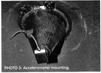
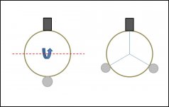
Removing the accelerometer from the signal chain and replacing it with the microphone and the 13Hz anamoly disappears. So it must be related to a motion of the cone that the accelerometer is feeling that doesn't result in a change in the average motion of the whole cone. This brings to mind your comments back in post # 2 about when tapping the cone sometimes it felt soft and sometimes hard. I had suggested in post # 10 that this might be due to a rocking mode being picked up by the accelerometer from its slightly offcenter position.
Your mounting method on the edge of the voice coil is not unusual, although as you pointed out the air volume of your box is much larger than typical. This might be related to why the rocking mode is seen.
You might try replacing the single counter-weight positioned opposite the ACH-01 with two positioned at +/-120 degrees to hopefully discourage any cone rocking. (Attachment #1).
Alternatively, you could build a small platform for mounting the accelerometer that attaches to the perimeter of the voice coil and centers the accelerometer mass over the line of action of the voice coil force. You can see an example of this in the Art and Jac Brown article(Attachment #2) and in the Paradigm servo subwoofers(Attachment #3)
>>>
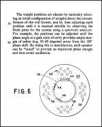
I just remembered that Velodyne mentions "tuning" phase response with weights attached to the voice coil in the patent US4727584.
Relevant excerpt can be seen in Attachment #4.
<<<
Attachments
Last edited:
Thank you, thank you, thank you!
I have played around with the system today and learned that it is indeed some cone rocking going on. While this a good thing when it comes to phase margin it does create problems when my servo circuit is sending my amp to clipping with its huge 13Hz signals.

I am tempted to insert a 13Hz twin-T notch filter in the accelerometer feedback loop, I'll try and let you know.
If that also fails I think my best option is to build a new accelerometer platform.
I have played around with the system today and learned that it is indeed some cone rocking going on. While this a good thing when it comes to phase margin it does create problems when my servo circuit is sending my amp to clipping with its huge 13Hz signals.
I am tempted to insert a 13Hz twin-T notch filter in the accelerometer feedback loop, I'll try and let you know.
If that also fails I think my best option is to build a new accelerometer platform.
In the case of measuring with the accelerometer, is the MF still active?
There is mic phase shift arising from all kinds of soundwave distances too.
Gotta say, my intuition still favours finding the 13 Hz in the electronics... but evidence is evidence.
Ben
There is mic phase shift arising from all kinds of soundwave distances too.
Gotta say, my intuition still favours finding the 13 Hz in the electronics... but evidence is evidence.
Ben
Twin-T nothc filter
So I made a twin.T notch filter. First at 13Hz, and then at 11Hz which gave better results. Adding it in the accelerometer feedback chain did not help nearly as much as adding it on the output before fed to the LM3886. I don't know why.
The huge signal (still present) is now reduced pretty much before sent to the amplifier. But solving one thing creates others 🙁
While the system now does impressive things with single 70Hz bursts I still have have 17Hz ringing and sometimes rather large cone movements at 3-4Hz when playing music. Still no oscillations however.

Plot 1. MF OFF. 70Hz pulse. Red = mic @ 5”. Blue= from soundcard. We can see that the recorded signal from the microphone is quite different from the input signal. SPL=117dB

Plot 2. MF ON. 70Hz pulse. RED= mic @ 5”. Blue= from soundcard. We can see that the sound recorded from the microphone tracks the input signal quite well. This is the really good part along with the lower distortion. 🙂 SPL 114dB. The SPL is lower here since the cone is not allowed the overshoot.

Plot 3. MF ON. Blue= from soundcard (same signal level as in plot 2). RED = signal sent to woofer from servo circuit.
The peak voltage sent to the LM3886 is 1V and equals 22V peak on the speaker terminal. It is interesting to see that in fact zero negative signal is sent to the woofer and still the sound pressure tracks the input signal as can be seen in Plot 2 above. The speed of the cone alone is enough to produce the sound while the servo circuit is just breaking it by holding the voltage around zero.
I still have problems with ringing after the pulse at a frequency of 17,3Hz as can be seen on the two vertical markers. But this is much less now with the twin-T 11Hz filter.
For those interesten in seeing how the signal looks before and after the notch filter:

Plot 4. Signal before and after notch filter with a 70Hz pulse to start the show.
I am going to play around a little with the system as it is and see if I can make it good enough for permanent use and give you a report. But eventually I think I will try to mount the accelerometer on a cone like Jac did.
So I made a twin.T notch filter. First at 13Hz, and then at 11Hz which gave better results. Adding it in the accelerometer feedback chain did not help nearly as much as adding it on the output before fed to the LM3886. I don't know why.
The huge signal (still present) is now reduced pretty much before sent to the amplifier. But solving one thing creates others 🙁
While the system now does impressive things with single 70Hz bursts I still have have 17Hz ringing and sometimes rather large cone movements at 3-4Hz when playing music. Still no oscillations however.
Plot 1. MF OFF. 70Hz pulse. Red = mic @ 5”. Blue= from soundcard. We can see that the recorded signal from the microphone is quite different from the input signal. SPL=117dB
Plot 2. MF ON. 70Hz pulse. RED= mic @ 5”. Blue= from soundcard. We can see that the sound recorded from the microphone tracks the input signal quite well. This is the really good part along with the lower distortion. 🙂 SPL 114dB. The SPL is lower here since the cone is not allowed the overshoot.
Plot 3. MF ON. Blue= from soundcard (same signal level as in plot 2). RED = signal sent to woofer from servo circuit.
The peak voltage sent to the LM3886 is 1V and equals 22V peak on the speaker terminal. It is interesting to see that in fact zero negative signal is sent to the woofer and still the sound pressure tracks the input signal as can be seen in Plot 2 above. The speed of the cone alone is enough to produce the sound while the servo circuit is just breaking it by holding the voltage around zero.
I still have problems with ringing after the pulse at a frequency of 17,3Hz as can be seen on the two vertical markers. But this is much less now with the twin-T 11Hz filter.
For those interesten in seeing how the signal looks before and after the notch filter:
Plot 4. Signal before and after notch filter with a 70Hz pulse to start the show.
I am going to play around a little with the system as it is and see if I can make it good enough for permanent use and give you a report. But eventually I think I will try to mount the accelerometer on a cone like Jac did.
Last edited:
- Home
- Loudspeakers
- Subwoofers
- Analog Servo Sub