A StroboTac, manufactured long ago by General Radio of Massachusetts, has a bright strobe light. It is triggered either by a pulse (I use it to time my motorcycle sparks as the world's greatest timing light triggered just by emanations from the wires), an external oscillator, or its own internal calibrated oscillator.
For your purposes, with or without this fancy gear, you'd flash a tiny bit out of synch with the driver. That gives the illusion of the cone moving in and out in "slow motion" at the beat frequency. Just an illusion since it really is successive (or multiple) cycles that are getting illuminated.
It is just your eyeball (with magnification possible) doing the observation - so any rocking has to be humanly perceptible by eye.
I have some ancient test equipment including the StroboTac stolen from Columbia University and other places in New York City*.
Ben
*which I purchased dirt-cheap from a certain pawn shop in Cooper Square around 1964... after the name plate was removed by the thief.... of course. I didn't get to use Bell Labs' gear for a few years later.
Last edited:
Strobo test
The sun has finally gone down and it is totally dark in my basement. Time to put the stroboscope to work.
I must say I am amazed at how good this works! The woofer looks like it is 100% standstill even when it is moving 1" in and out. Carefully moving my finger towards the cone suddenly hits me with its truly invisible "macic field". 😀
I have been using stroboscope before on my car so this is not new to me. But I had not anticipated that this LED mockup would work so good.
The LED I am using is a 720mA 36V 2000lm COB LED:
30W 720mA Strip Bar COB SMD LED Light Lamp 36-45V 2000lm-Warm White $19.67 Free Shipping @GoodLuckBuy.com
At 36.6V the current is about 700mA so I dont need a series resistor or a current regulator.
I can adjust the strobe pulse from 1.5ms down to about 100us if it is dark in the room. At 300us it's OK with normal room lighting. At 1.5ms the light output is really powerful but I loose a little focus if the cone is in the middle (at maximum speed)

I learned today that rise and fall time of LED are actually in the ns range. Is LED superior to strobe light?
What is the flash duration of a old fashioned stroboscope? I could not find any info on the net.
Anyway. I was not able to identify any rocking or movement at all.
* I have tried frequencies from 10Hz to 30Hz.
* Different pulse witdh for more or less light.
* I have tried with the flash triggering when the cone is at different positions of the curve.
* I have tried Ben's suggestion with external trigger slightly off woofer frequency. I could clearly see the slow motion of the cone but nothing unusual.
But then again, my loop gain is high and just the smallest (not visible to my eye) amount of in-phase 13Hz will be amplified and sent back in phase.
I'll see what to do next later after being sidetracked by a not-so-great gopro and a really fascinating strobo. Thanks for the tip guys 🙂
Armand
I am going to make a PCB for this and put it in a nice box.

The sun has finally gone down and it is totally dark in my basement. Time to put the stroboscope to work.
I must say I am amazed at how good this works! The woofer looks like it is 100% standstill even when it is moving 1" in and out. Carefully moving my finger towards the cone suddenly hits me with its truly invisible "macic field". 😀
I have been using stroboscope before on my car so this is not new to me. But I had not anticipated that this LED mockup would work so good.
The LED I am using is a 720mA 36V 2000lm COB LED:
30W 720mA Strip Bar COB SMD LED Light Lamp 36-45V 2000lm-Warm White $19.67 Free Shipping @GoodLuckBuy.com
At 36.6V the current is about 700mA so I dont need a series resistor or a current regulator.
I can adjust the strobe pulse from 1.5ms down to about 100us if it is dark in the room. At 300us it's OK with normal room lighting. At 1.5ms the light output is really powerful but I loose a little focus if the cone is in the middle (at maximum speed)
I learned today that rise and fall time of LED are actually in the ns range. Is LED superior to strobe light?
What is the flash duration of a old fashioned stroboscope? I could not find any info on the net.
Anyway. I was not able to identify any rocking or movement at all.
* I have tried frequencies from 10Hz to 30Hz.
* Different pulse witdh for more or less light.
* I have tried with the flash triggering when the cone is at different positions of the curve.
* I have tried Ben's suggestion with external trigger slightly off woofer frequency. I could clearly see the slow motion of the cone but nothing unusual.
But then again, my loop gain is high and just the smallest (not visible to my eye) amount of in-phase 13Hz will be amplified and sent back in phase.
I'll see what to do next later after being sidetracked by a not-so-great gopro and a really fascinating strobo. Thanks for the tip guys 🙂
Armand
I am going to make a PCB for this and put it in a nice box.
Duration varied alot depending on the tube and drive circuitry. For the tube I used it was about 10uS.What is the flash duration of a old fashioned stroboscope? I could not find any info on the net.
I've moved on from that and drive a 90 LED shop light with a circuit similar to yours.
Like you I was surprised at how "fast" modern LEDs are.
Anyway. I was not able to identify any rocking or movement at all...But then again, my loop gain is high and just the smallest (not visible to my eye) amount of in-phase 13Hz will be amplified and sent back in phase.
Are you testing open loop? or closed loop. I would stick with open loop for now.
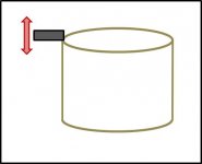
Looking back at your mounting method shown in post#1, is there any chance the accelerometer is vibrating like a cantilever beam? Perhaps with the woofer removed from its enclosure you could try the slow sweeps around 13Hz with the strobe synced to the drive signal to freeze the up and down motion and illuminate the accelerometer from under the basket to see if it is bending up and down relative to the voice coil reference position.
Attachments
Last edited:
You dont give up easily, do you ? 🙂
I'll take it out and have a look tomorrow.
Edit. I am measuring open loop.
I'll take it out and have a look tomorrow.
Edit. I am measuring open loop.
Last edited:
So I've been told 😉
Based on your open loop measurements, there has to be some kind of motion that the acceleromter is experiencing that the mic(which reacts to average acceleration of the whole cone) does not.
Based on your open loop measurements, there has to be some kind of motion that the acceleromter is experiencing that the mic(which reacts to average acceleration of the whole cone) does not.
The 13Hz hunt
Todays test.
1. Add a second accelerometer to the center of the dust cap
2. Add a second accelerometer off-center (over the internal one)
3. Add 5 grams off center
Results:
1. Measuring the new centre mounted accelerometer, the phase follows a second order filter. No 13Hz anomaly. (same as with microphone)
2. Measuring the off-centre mounted accelerometer, the phase also follows a second order filter and is the same as in test 1.
3. Measuring with the internal accel with added mass gives no change.
Phase plot.

Green = Internal accelerometer
Purple= New centre mounted accel
Blue = added off-centre mass (5g) measured with internal acc.
Red = New accel mounted above the internal one
The purple, blue and red plot have been offset for readability.
Picture of woofer in test 1 and 3

Picture of woofer in test 2

Conclusion
Test 1. No surprises here. the microphone measurement had already proved this
Test 2. Adding a second accelerometer on the cone just over the internal one should give same results as the internal one but its not. This supports bolserst suggestion of the cantilever beam theory.
Test 3. Adding off centre mass has no effect. This also supports bolserst suggestion of the cantilever beam theory.
Now its time to take out the woofer and have a look at the internal accelerometer with the stroboscope
Todays test.
1. Add a second accelerometer to the center of the dust cap
2. Add a second accelerometer off-center (over the internal one)
3. Add 5 grams off center
Results:
1. Measuring the new centre mounted accelerometer, the phase follows a second order filter. No 13Hz anomaly. (same as with microphone)
2. Measuring the off-centre mounted accelerometer, the phase also follows a second order filter and is the same as in test 1.
3. Measuring with the internal accel with added mass gives no change.
Phase plot.
Green = Internal accelerometer
Purple= New centre mounted accel
Blue = added off-centre mass (5g) measured with internal acc.
Red = New accel mounted above the internal one
The purple, blue and red plot have been offset for readability.
Picture of woofer in test 1 and 3
Picture of woofer in test 2
Conclusion
Test 1. No surprises here. the microphone measurement had already proved this
Test 2. Adding a second accelerometer on the cone just over the internal one should give same results as the internal one but its not. This supports bolserst suggestion of the cantilever beam theory.
Test 3. Adding off centre mass has no effect. This also supports bolserst suggestion of the cantilever beam theory.
Now its time to take out the woofer and have a look at the internal accelerometer with the stroboscope
I was not able to see any movement of the accelerometer with the stroboscope. 🙁
I tried 6Hz 10Hz, 12Hz, 13Hz, 15 Hz 27Hz and 30Hz. I tried locking the trigger to top, middle and top position of the cone.
But then again, would not the accelerometer always be in it's same position at the same point on each wave??
I made a sweep from 10 to 16 and back to 10 Hz with a total duration of 2 seconds that was played on loop. The cone appearead to move slowly up and down but the accelerometer followed nicely without any visible anomalies.
One interesting thing I noteced was that the 13Hz anomaly now had moved down to 6,5Hz. Why is that?? It must rule out that the problem is the cable connected to the woofer, right? The cable is also glued to the cone several mm after leaving the accelerometer.

This is measured with the internal accelerometer with woofer in free air. The high pass filter of the accel opamp is included in this response
Bedtime..
Armand
I tried 6Hz 10Hz, 12Hz, 13Hz, 15 Hz 27Hz and 30Hz. I tried locking the trigger to top, middle and top position of the cone.
But then again, would not the accelerometer always be in it's same position at the same point on each wave??
I made a sweep from 10 to 16 and back to 10 Hz with a total duration of 2 seconds that was played on loop. The cone appearead to move slowly up and down but the accelerometer followed nicely without any visible anomalies.
One interesting thing I noteced was that the 13Hz anomaly now had moved down to 6,5Hz. Why is that?? It must rule out that the problem is the cable connected to the woofer, right? The cable is also glued to the cone several mm after leaving the accelerometer.
This is measured with the internal accelerometer with woofer in free air. The high pass filter of the accel opamp is included in this response
Bedtime..
Armand
Been silent not to disturb the wonderful braindump/share going on overhere, just wanted you to know I bumped into this Philips Technical Review which confirms Armands findings :
see page #5 of the originating pdf, 1968 😱
http://mfb.piratelogic.nl/data/docs/PTR.1968.MFB.motionalfeedbackspeakers.en.pdf
er is ook een nederlandse versie.
An externally hosted image should be here but it was not working when we last tested it.
see page #5 of the originating pdf, 1968 😱
http://mfb.piratelogic.nl/data/docs/PTR.1968.MFB.motionalfeedbackspeakers.en.pdf
er is ook een nederlandse versie.
Last edited:
This is how I mounted the ac01h into my 537 prototype, dunno if this will work for the XLS since you will need a ventilated polepiece (in dutch poolkernboring, couldn't find the exact translation) because the pcb on which the ach01 was mounted effectively blocks any airflow. The surplus soldering was from earlier experiments with piezo buzzers. I used genuine speaker litze wire to connect the sensor to the outside world as I don't trust the ACH01/02 cable, I've seen to many cable breaks after prolonged use, especially with those long stroke types ....
An externally hosted image should be here but it was not working when we last tested it.
Last edited:
I indeed had to drill some holes in my mounting disc in order not to obstruct the airflow. Another woofer I am evaluating does have the perforated voice coil carrier, which does make things easier.
@chriscam, how does the ach-01 perform with just power, ground and signal "tied" to gnd? Did you implement the advised gainstage somewhere in the signal path?
@chriscam, how does the ach-01 perform with just power, ground and signal "tied" to gnd? Did you implement the advised gainstage somewhere in the signal path?
@superr this is the 537 schematic, being the true pirate I am 😎 it's heavily based upon the original Philips 22AH587 schematic dating back into the eigthies hence the lack of opamps and highly discrete setup. I did swap the darlington based amps for 3886 / 7293 to save boardspace. All I had to do to make things work with the ACH01 was to increase the gain of T18 a little bit. Biggest advantage of the way the ACH01 is setup is that only 2 wires are needed to transport the feedback signal.
ps we're working on a more modern incarnation using opamps and switchers, see here - sorry folks, dutch only for now but we're working on an intl wiki.
An externally hosted image should be here but it was not working when we last tested it.
ps we're working on a more modern incarnation using opamps and switchers, see here - sorry folks, dutch only for now
but we're working on an intl wiki.
Last edited:
Non-axial forces.... oh my God..... OMG..... I hope none of these are also incorporeal. Do you suppose these non-axial forces come from aliens attacking Planet Earth from outside the known solar system?
Joking aside, the 13-Hz non-axial resonance (rocking or something to do with the acclerometer packaging or maybe in the electronics) may not be a bad problem. I say "resonance" because it seems to be hiding out in the system and appearing when stimulated. Paradoxically, since the 13-Hz isn't part of the loop (it can't be controlled by the feedback signal to the voice coil and so doesn't loop around again), it might just hang around as an inaudible nuisance (except for Doppler distortion)... but not a threat to stability.
Why have I always (until recently) thought that the nice low-impedance, low component count, "voice-coil in a bridge" approach made more sense than using an inexpensive accelerometer adding mechanical stress to a precisely manufactured cone? Is it because I am more concerned about acoustics and mechanical design issues while others are more interested in DSP and trick processing? Is there a middle ground?
Perhaps getting the mounting sorted out is just a small bump in the road to good accelerometer MF. Hope so. Armand's results look good. But so do 60 years of good results with the bridge method.
Ben
Last edited:
One interesting thing I noteced was that the 13Hz anomaly now had moved down to 6,5Hz. Why is that??
13Hz in the cabinet, 6,5Hz in free air...hmmmm...
Assuming this is not a one time event, and you can repeat results of 13hz when woofer is returned to its cabint, it appears that whatever the resonance mode is, it is responding to increased stiffness from the air spring acting on the woofer cone.
I was not able to see any movement of the accelerometer with the stroboscope.
I tried 6Hz 10Hz, 12Hz, 13Hz, 15 Hz 27Hz and 30Hz. I tried locking the trigger to top, middle and top position of the cone. But then again, would not the accelerometer always be in it's same position at the same point on each wave??
"If" there is a cantilever resonance:
The accelerometer position relative to the lower surface of the cone would change.
Since the free air resonance is 6.5hz you would want to look just above and just below that frequency where the motion relative to the cone would be greatest.
Just above resonance at say 8 Hz the motion would be 180 degrees out of phase with the cone. So as you moved the trigger from the middle cone position to the top position you would see the separation distance between the bottom surface of the cone and accelerometer increase, and as you moved toward the bottom position the separation should decrease. Just below resonance at perhaps 5 Hz you would see the opposite trend since the cantilever vibration would be in phase with the cone motion.
(let me know if the words don't make sense, and I can try and put together some drawings)
Unfortunately it IS part of the feedback loop. It results in the feedback loop "thinking" the woofer cone motion has increased error at 13Hz when it really doesn't. Mic measured response for open loop would not show the 13Hz ringing at the end of transients like the closed loop measurements. You are right that in Armand's case it doesn't seem to be severe enough to have concern for stability. But if we don't really understand it, I don't think we can say with certainty that is poses no stability risk for other similar MFB setups....since the 13-Hz isn't part of the loop (it can't be controlled by the feedback signal to the voice coil and so doesn't loop around again), it might just hang around as an inaudible nuisance (except for Doppler distortion)... but not a threat to stability.
Last edited:
Chriscam:
Thank you for that document. It seems thay have had the same problem before. I'm not sure exactly what those non-axial forces are. But I have noticed that the ACH-01 is sensitive to bending forces and it is recommended to mount it on a rigid surface. (Which is *far* from what I have done.)
From the data sheet:
In an effort to keep the product cost low, the ACH-01 uses a ceramic substrate as the
mounting base. Because of this, the ACH-01 is susceptible to base strain and
temperature transient effects. A mechanically rigid and thermally non-conductive
mounting surface is highly recommended to limit these effects.
Could you please elaborate a little about how the accel performs with only two wires? Can it swing to 150g both ways? I seem to remember something with a "pinch-off" voltage or something.
And please make a english wiki on your project 🙂
Ben:
We can rule out electronics as the source for the 13Hz anomaly. When doing my test with another centre mounted accel which did not have the 13Hz anomaly, I used the same electronics.
I lean towards bending forces as the source for the measurement error.
bolserst:
After searhing for movement with my strobo again today I gave up and it is back in its box and the frequency anomaly is now back to 13Hz.
In your cantilever theory you are talking about a 180 degree phase shift. But that is not the case. The phase shift we see is more complex and since it is impossible to explain I have made a movie of my scope, measuring a sweep from 1Hz to 20Hz with 60 seconds duration. The servo is not active,
The blue curve is the input signal and the red curve is the accelerometer measured directly on the accelerometer output. NOTE: I made sure to set the scope to DC to avoid the added phase shift in the scope when on AC. That is why I had to zoom so much in on the curves. (Luckily I have a 12-bit scope) In the video you can see the actual frequency at the bottom left.
I wish I had posted this video earlier since it might shed some light on what happens around 13Hz. We can see that the average phase shifts 90 degrees but there are other waveforms also. Have a look and judge by yourself.
I lean towards that all of this is caused by strain is applied to the sensor from the cone, and that that strain shifts when in the box and in free air because of the different strain on the cone.
Right click the link and click "save as" or similar.
http://home.ebnett.no/armand/Video/Servosub/scope sweep from 1 to 20 Hz.avi
Another thought as Ben also mentioned is that maybe this can be a good thing? If I can manage to get the 13Hz under control it does give me larger phase margin.
Starting to look like the "inexpensive" sensor is the culprit and source of the after-shock 13 Hz signal.
But the odd thing is that the MF should correct the sensor, as long as the system has the means (at 13 Hz or 6.5 Hz) of doing so. All the MF does is correct the accelerometer, not the cone.
But if it is non-axial mystery forces, the driver motor has no ability to correct anything that isn't just in-and-out, whether rocking or inside the accelerometer.
Ben
From the data sheet:
In an effort to keep the product cost low, the ACH-01 uses a ceramic substrate as the
mounting base. Because of this, the ACH-01 is susceptible to base strain and
temperature transient effects. A mechanically rigid and thermally non-conductive
mounting surface is highly recommended to limit these effects.
...
I lean towards bending forces as the source for the measurement error.
I had not noticed the mention of strain sensitivity in the ACH-01 datasheet before. That would certainly come into play with the bending forces generated in your current mounting method. And, these strains could be fairly substantial even if the motion of the accelerometer relative to the cone/voice coil is very small...too small to see with strobe light. I think you may have finally found the true source of the 13Hz anomaly.
I was not talking about the phase of the accelerometer output which is a combination of the acceleration of the cone + additional accelerometer motion + additional accelerometer strains. I was talking about the phase of the motion of a cantilevered object(the accelerometer) relative to the forcing function(the cone). This is exactly analogous to the motion of the cone relative to the driving force from the voice coil. Below resonance the cone position is in phase withe the driving voltage, above resonance the cone position is 180 degrees out of phase with the driving voltage. At resonance, it is in quadrature.bolserst:
After searhing for movement with my strobo again today I gave up and it is back in its box and the frequency anomaly is now back to 13Hz. In your cantilever theory you are talking about a 180 degree phase shift. But that is not the case. The phase shift we see is more complex...
Attached is a screen capture from a website where you can play with mass-spring-damper motion when driven by a sinusoidal force. If the red dot represented the cone motion, the blue dot would be the motion of a cantilevered object. If the red dot is considered the voice coil current, then the blue dot would be the motion of the cone. Set the frequency of the forcing function(ie exciter frequency) to different positions on the the resonance curve and play the animation to see how the red dot and blue dot move relative to each other.
Forced oscillations (resonance)
I tend to agree with you...always best to follow datasheet instructions right? 😉I lean towards that all of this is caused by strain is applied to the sensor from the cone, and that that strain shifts when in the box and in free air because of the different strain on the cone.
Of all the theories we have talked about, this seems the most plausible given the mounting method, all your measured data, and strobe light observations.
...improper mounting of a very low distortion sensor...inexpensive or not.Starting to look like the "inexpensive" sensor is the culprit and source of the after-shock 13 Hz signal.
If the "mystery" internal strain can be excited by the cone motion in an open-loop situation, feedback from the accelerometer will drive the cone so as to zero-out this strain. But it the process, the cone will be moved in a fashion that does not match the input signal or mic measured pressure response.if it is non-axial mystery forces, the driver motor has no ability to correct anything that isn't just in-and-out, whether rocking or inside the accelerometer.
Attachments
Last edited:
I'll stick to my intuitive opinion: even if motion of the cone initiates/excites the error, doesn't always mean the MF can fix it.snip If the "mystery" internal strain can be excited by the cone motion in an open-loop situation, feedback from the accelerometer will drive the cone so as to zero-out this strain. But it the process, the cone will be moved in a fashion that does not match the input signal or mic measured pressure response.
And I'll add again, we are talking about systems crying out for MF control yet unsuitable for negative feedback because we are trying to make them work beyond their band of good behaviour.
Ben
I see.I was not talking about the phase of the accelerometer output which is a combination of the acceleration of the cone + additional accelerometer motion + additional accelerometer strains. I was talking about the phase of the motion of a cantilevered object(the accelerometer) relative to the forcing function(the cone).
I am going to put the XLS and the 13Hz problem on the shelf for a while and move on to another woofer.
I want to build either two dipole towers or a "Double Bass Array". In either case I need a lot of drivers, and since I cannot afford spending too much money I have bought 16 cheap 15" woofers. ( I am sure to Ben's disappointment. No offence Ben 😀 ) Now I want to see how they perform with MF. I'll keep you posted and I can assure you the accel will be mounted rock solid in the centre of the cone somewhere.
I have no problem at all with "inexpensive" and second-hand things generally (my amps come from the charity or second-hand sources) but I draw the line when it is a criterion of performance like a sensor and/or things where the spec doesn't tell the whole story (that's definitely relevant here, eh?).I see.
I am going to put the XLS and the 13Hz problem on the shelf for a while and move on to another woofer.
I want to build either two dipole towers or a "Double Bass Array". In either case I need a lot of drivers, and since I cannot afford spending too much money I have bought 16 cheap 15" woofers. ( I am sure to Ben's disappointment. No offence Ben 😀 ) Now I want to see how they perform with MF. I'll keep you posted and I can assure you the accel will be mounted rock solid in the centre of the cone somewhere.
I think mixed-bass is smart. No need for L and R bass signal or putting the boxes L and R. But many important benefits using heterogeneous enclosures and locations, not two-of-the-same subs.
Let us know of your progress.
Ben
- Home
- Loudspeakers
- Subwoofers
- Analog Servo Sub