If what is causing in sampling modulation is a clock multiplying with the signal, than to demodulate should also be a clock the divider.
On the other hand if the blue beat signal is dividing back the delta, I get back my clock.
On the other hand if the blue beat signal is dividing back the delta, I get back my clock.
When the sampler excedes four samples per cycle, that is above 11khz, in time domain all frequencies get described by the Nyquist frequency with it's amplitude modulation. This what in shown at 20khz.
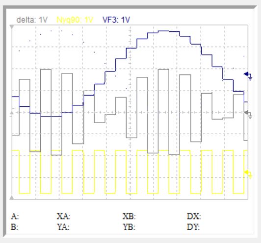
In other words I have only two information to extract the frequencies above 11khz, the Nyquist, yellow and the beat, blue signals.
To extract the image which is sin(N+B) by trigonometry is equal to
sinN × cosB + cosN × sinB. This what the Hartley's modulator was doing with QPS filter providing the sinB and the cosB.
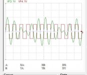
To deal with this function I don't need a sampler, just adding two signals 20k and 24khz, I get the same result. The two frequencies disappear and I get the average of the sum (20+24)/2=22khz and difference (24-20)/2=2k.
As shown bellow the 22khz square wave overlaid on the sum of the two frequencies.
In other words I have only two information to extract the frequencies above 11khz, the Nyquist, yellow and the beat, blue signals.
To extract the image which is sin(N+B) by trigonometry is equal to
sinN × cosB + cosN × sinB. This what the Hartley's modulator was doing with QPS filter providing the sinB and the cosB.
To deal with this function I don't need a sampler, just adding two signals 20k and 24khz, I get the same result. The two frequencies disappear and I get the average of the sum (20+24)/2=22khz and difference (24-20)/2=2k.
As shown bellow the 22khz square wave overlaid on the sum of the two frequencies.
Attachments
Last edited:
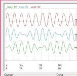
Once two near frequencies are mixed it looks to be as difficult to separate salt from water, no it isn't.

The central trace is 20khz mixed with 24khz the same as the above post. The lower trace is the same mixed but delayed and inverted so that the maxima is at coincidence with the minima. the upper trace, 20khz is the sum of the two under ones.
The central trace is 20khz mixed with 24khz the same as the above post. The lower trace is the same mixed but delayed and inverted so that the maxima is at coincidence with the minima. the upper trace, 20khz is the sum of the two under ones.
Attachments
It looks like your delay is 125 us, so you now have a comb filter that suppresses any integer multiple of 8 kHz.
It doesn't work for all frequencies although I am doing what the Hartley modulator does.
Frequencies above 11khz have only 3 defined points and cannot be treated as the lower ones. What hurts me that the sampler can get at these frequencies the peak voltage hence no attenuation should be at the result, The sinc says this sacred number forget it.
I will go back to 3 way treatment and mix DC-50, 50-10k, 10k-21k.
Last edited:
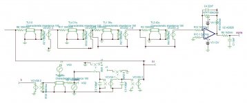
This is 3 notch comb filters that cut -30db and more the images. the output is the one that will will make 10-20khz. What is admirable with this filter, it is constant phase with a delay of 53.6us from 10k to 20k. If it could be 56.6u than 2.5 fs could be used as actually I have 2fs only.
Attachments

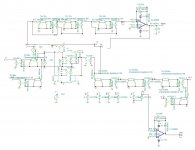
This is the digitalized version feeding with S/H. It has superb transients, constant delay, miraculously exactly 3fs that I can add in my hardware just to add extra DAC for high frequency. Of course it needs level shaping, crossover filtering and sinc droop compenation.
There is a pre built C-switched filter LTC1064-7 "better than Bessel filter" of 8th order low pass, anyone has an idea about it.
https://www.analog.com/media/en/technical-documentation/application-notes/an56.pdf
bellow 10khz snd 20khz.
Attachments

Reconstructing the high frequencies can be achieved by bringing extra points to the only 3 sampled sacred ones. The filter of precedent post gives two valuable points.

The 3 s points are the sacred ones two on one phase, one on the other, the filter provides the zero crossing points z and also the derivative of the sigma tells me at what time T happens the maxima and the minima. As the frequency cannot exceed 20khz, only one maxima or minima can occur between two zeros.
If I can get the value of the maxima/minima, then I get on each cycle 8 points to reconstruct by cubic spline. To get the minima/maxima values, I need to equalize the filter response no matter the phase shift and sample the values.
Ahh, what an adventure.
The image bellow are the original wave, the sampled and the sigma.
Passing suddenly from SSB technic to interpolation one without accomplishing a successful result, I got hunted by culpability, even in my dreams, it forcing me since two days in insomnia. For the sake of peace in mind, I will return back for a while accomplish the version that worked well up to 17khz, to bundle it up at best, and empty my brain from this subject.
The new technic will take back from the output where it was perfected up to 10khz, add new data/time points harvested from the delay-notches and submit time/voltage interpolation for the second time , by this all the sacred values will be respected.
The new technic will take back from the output where it was perfected up to 10khz, add new data/time points harvested from the delay-notches and submit time/voltage interpolation for the second time , by this all the sacred values will be respected.
Last edited:
I adjusted the QPS capacitors using my nose (pifometer) and arrived a very good result up to 18khz

It doesn't destroy the transient of 20khz, although it enhances slightly.

The 10khz is not very brilliant but it's image is at 34khz, a 2nd order filter can take care of.
I will try using my pifometer instead of Matlab, to add a third QPS stage my be I can adjust the 20khz.
It doesn't destroy the transient of 20khz, although it enhances slightly.
The 10khz is not very brilliant but it's image is at 34khz, a 2nd order filter can take care of.
I will try using my pifometer instead of Matlab, to add a third QPS stage my be I can adjust the 20khz.
Attachments
When you write out the transfer functions of the three comb filters of post #187 and multiply them, you end up with a kind of FIR filter response that is point symmetrical in the centre, has eight nonzero entries and only has coefficients +1 and -1. That would be very simple to implement as a FIRDAC using eight DACs with symmetrical outputs, connecting all outputs in parallel with a swap of the positive and negative sides for the -1.
I've checked if I could come up with an eight-tap FIRDAC with delays of multiples of 1/352800 seconds, coefficients +1 and -1, that together with a continuous-time integrator approximates the main lobe and the nearest side lobes of the sinc impulse response you need for reconstruction. The best result I found was:
Delays and weights:
0/352800 s, -1
2/352800 s, +1
5/352800 s, +1
8/352800 s, +1
16/352800 s, -1
19/352800 s, -1
22/352800 s, -1
24/352800 s, +1
Group delay: constant at 12/352800 s.
The signal to noise ratio will probably be awful due to the differentiating in the FIRDAC and integration at the end. Attached is the calculated frequency response.
Attachments

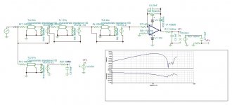
I modified slightly the filter to get precisely 2fs delay, the output RC fine adjusts.
I am sure this filter can be implemented as it is in digital world without translating it into equivalent FIR, to extract extra points asynchronous to fs only.
Concerning the SSB, 3 order QPS destroys the transient of all frequencies. Now I am consoled that all has been done for this technic, after all 18khz with an extra Bessel filter at 20khz is not perfect but far superior to existing versions.
Attachments
Last edited:
I am sure this filter can be implemented as it is in digital world without translating it into equivalent FIR, to extract extra points asynchronous to fs only.
Implementing it digitally is surely possible when you oversample, but I thought you were opposed to oversampling.
My calculations for post #191 were wrong, as I forgot the zeroth order hold function. To be continued.
No, it will not work digitally. The zero crossing and the maxima points are asynchronous which will require as you mentioned oversampling at very high bit rate.
Talking about digital, have you ever though about continuously variable slope single bit stream. Just before the arrival of CD format, we were numerous to use CVSD to record 16channel 20khz on VHS cassette, using only 150khz single bit. The system adapts by itself the slope to match the level. As in music spectrum, the amplitude decreases with frequency 3db/octave and the slope increases by 6db/octave, by increasing/decreasing at low speed the slope lets say 1khz for 500khz bit rate the slope can perfectly adapt to most high dynamic, sudden increase/decrease of sound level. Of course this can happen in symphonic music, modern ones are very low dynamic. The CVSD coding occurs digitally and the decoding by hardware as MC34115. Throw an eye on the datasheet, might give you new ideas about single bit stream or DSD.
Talking about digital, have you ever though about continuously variable slope single bit stream. Just before the arrival of CD format, we were numerous to use CVSD to record 16channel 20khz on VHS cassette, using only 150khz single bit. The system adapts by itself the slope to match the level. As in music spectrum, the amplitude decreases with frequency 3db/octave and the slope increases by 6db/octave, by increasing/decreasing at low speed the slope lets say 1khz for 500khz bit rate the slope can perfectly adapt to most high dynamic, sudden increase/decrease of sound level. Of course this can happen in symphonic music, modern ones are very low dynamic. The CVSD coding occurs digitally and the decoding by hardware as MC34115. Throw an eye on the datasheet, might give you new ideas about single bit stream or DSD.
Last edited:
Correction to post #191:
Delays and weights:
0/352800 s, -1
3/352800 s, +1
4/352800 s, +1
7/352800 s, +1
15/352800 s, -1
18/352800 s, -1
19/352800 s, -1
22/352800 s, +1
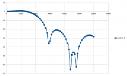
Group delay 11/352800 s plus 1/88200 s from zeroth-order holds over 1/44100 s. Frequency response including zeroth-order holds over 1/44100 s as attached, horizontal scale in Hz, vertical in dB.
Delays and weights:
0/352800 s, -1
3/352800 s, +1
4/352800 s, +1
7/352800 s, +1
15/352800 s, -1
18/352800 s, -1
19/352800 s, -1
22/352800 s, +1
Group delay 11/352800 s plus 1/88200 s from zeroth-order holds over 1/44100 s. Frequency response including zeroth-order holds over 1/44100 s as attached, horizontal scale in Hz, vertical in dB.
Attachments
Talking about digital, have you ever though about continuously variable slope single bit stream. Just before the arrival of CD format, we were numerous to use CVSD to record 16channel 20khz on VHS cassette, using only 150khz single bit. The system adapts by itself the slope to match the level. As in music spectrum, the amplitude decreases with frequency 3db/octave and the slope increases by 6db/octave, by increasing/decreasing at low speed the slope lets say 1khz for 500khz bit rate the slope can perfectly adapt to most high dynamic, sudden increase/decrease of sound level. Of course this can happen in symphonic music, modern ones are very low dynamic. The CVSD coding occurs digitally and the decoding by hardware as MC34115.
I never did anything with continuously variable slope delta modulation myself. I did use plain old first-order delta modulation once: way back in 1987 I built a doorbell using four 41256 DRAM chips and a simple delta modulator, which I still use today. You can record a sound of about four seconds which will then be played back when there's someone at the door. The sound quality is poor, lots of noise and idle tones, but good enough for the application.
In 1997-2000 I built a field memory recorder for the local radio station here. Its CODEC chip could work in 16 bit PCM mode, but also in 4 bit ADPCM format. ADPCM is rather similar to CVSD, but using more than 1 bit per sample.
It surprised me how good 41.666... kHz 4 bit ADPCM sounded. Out of curiocity, I wrote software so I could do a randomized blind test with ten randomized trials per music fragment. It turned out that I didn't hear any difference with most types of music, both popular and classical, but I could hear it very clearly on Tracy Chapman, Behind the wall, just one female voice with silence between the lines. Every time she continued singing, I heard a short but clear distortion.
On post 188 I was talking about interpolating 3 sacred samples along with zero crossing and lmaxl values. I know when these maximas occur, I wanted to hunt the values by filtering.
An hour of stroll on the deserted beach gave me a better idea.
The derivative of the required interpolated output, I know its zero crossing points which are the same when maximas occur. I know when the maximas of the derivative occur, which are the harvested zero crossing points. The lmaxl values of the derivatives, which are the zero crossing slopes, I can find out by the sacred samples and the zero crossing time. by this I can interpolate the derivative and integrate.
My task now is to calculate the zero crossing slope, and "klaar is Kees".
Last edited:
It happened something miraculous.
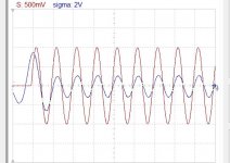
On preceding post I was concerned to get the slope of the zero crossing to have the lmaxl of derivative. If I need to work with derivatives so I decided to interpolate the derivative of the signal. The interpolation of the derivative requires one extra delayed sample, so it is more precise. Once I applied the cubic spline, the high frequencies instead of carrying the image they are carring the beat??? Have a look this is 15khz.

The beat I can get it to subtract very easily.
On preceding post I was concerned to get the slope of the zero crossing to have the lmaxl of derivative. If I need to work with derivatives so I decided to interpolate the derivative of the signal. The interpolation of the derivative requires one extra delayed sample, so it is more precise. Once I applied the cubic spline, the high frequencies instead of carrying the image they are carring the beat??? Have a look this is 15khz.
The beat I can get it to subtract very easily.
Attachments
- Home
- Source & Line
- Digital Line Level
- Analog Delta-Sigma interpolation DAC