
It's all greek to me 😉
While it could be fun to build something like this you can do a lot better most likely by purchasing something like a secondhand:
HP 3468A
Fluke 8050A
If you know where to look, functional ones can be had for less than US$50.
While it could be fun to build something like this you can do a lot better most likely by purchasing something like a secondhand:
HP 3468A
Fluke 8050A
If you know where to look, functional ones can be had for less than US$50.
Here is the schematic diagram and specifications
Thanks 🙂
Not to make it literally but to adapt the basic idea (specially the input attenuator and audio rectifier) using a couple Op Amps.
It can be easily done with a couple TL072 😀
Main problem and most expensive part is getting the proper 50uA meter, the rest is easy.
Just please translate and post any adjustment/calibration procedure 🙂
I guess the switchable 100r and 324r resistors chance scale from multiples of 2 to multiples of 6 ?
As of the schematic, I didn't understand a word !!!!!!!
It's in ...... German !!!!!!!!! 😱
50uA, is the meter current for what we used to call "20,000 ohms per volt" when looking at analog volt meters. Any meter with that rating will have a 50uA movement. COnvert grandpa's old V-O-M.
Agree we can buy everything,but what we doing here in a diy site?🙂It's all greek to me 😉
While it could be fun to build something like this you can do a lot better most likely by purchasing something like a secondhand:
HP 3468A
Fluke 8050A
If you know where to look, functional ones can be had for less than US$50.
I see many fluke 8050A ebay sellers but all from USA.
Last edited:
Exactly!!!50uA, is the meter current for what we used to call "20,000 ohms per volt" when looking at analog volt meters. Any meter with that rating will have a 50uA movement. COnvert grandpa's old V-O-M.
like a secondhand:
HP 3468A
Fluke 8050A
My favorite is still the hp 400F 😀
Voltage range: 0.1 mV to 300 V F.S. 14 ranges
Frequency range: 20 Hz - 4 MHz
Input impedance: 10 MO on all ranges <30pF to <15 pF depending on ranges
Cheers
Hp
Last edited:
In my simplistic THD meter, I have used an alternative ideal rectifier, which is ground-referenced and normalized.
This allows the use of practically any instrument, including cheap LCD millivoltmeter modules:
http://www.diyaudio.com/forums/equipment-tools/207513-simplistic-distortion-meter.html
This allows the use of practically any instrument, including cheap LCD millivoltmeter modules:
http://www.diyaudio.com/forums/equipment-tools/207513-simplistic-distortion-meter.html
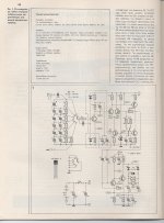
The input adjustable attenuator uses Capacitors in parallel to the resistors.
Why?
Is this to use a capacitive divider ladder to compensate for unknown parasitic capacitances that we know must exist?
I like the 12r||150r for the bottom step to give the required 11r1111 repeating to ensure the bottom step achieves the necessary -20dB attenuation and all the steps give the 20dB increments.
What about just building the attenuator and amplifier upto and including C20||C21 and using that as a pre-amp to feed an rms reading DMM?
Is S2 a gain set switch?
Is S2 a gain set switch?
The input adjustable attenuator uses Capacitors in parallel to the resistors.
Why?
Is this to use a capacitive divider ladder to compensate for unknown parasitic capacitances that we know must exist?
I like the 12r||150r for the bottom step to give the required 11r1111 repeating to ensure the bottom step achieves the necessary -20dB attenuation and all the steps give the 20dB increments.
1)Capacitors in parallel to resistors used for compensation .In that way attenuator remain linear for frequencies greater than 500 kHz.What about just building the attenuator and amplifier upto and including C20||C21 and using that as a pre-amp to feed an rms reading DMM?
Is S2 a gain set switch?
2)You can't do that.T7,T8 is a part of active rectifier.You need an A.C audio voltmeter to measure on C20//C21.
3)Yes S2 is a gain set switch.When S2 is in position 1 gain is 83 and when is in position 2 gain is 26.
Last edited:
Yes, DMM set to 199.9mVac measures AC voltage passing through C20||C21.2)You can't do that.T7,T8 is a part of active rectifier.You need an A.C audio voltmeter to measure on C20//C21.
The rectifier and readout is already inside the DMM.
DMM set to 199.9mVac measures AC voltage passing through C20||C21.Yes, DMM set to 199.9mVac measures AC voltage passing through C20||C21.
The rectifier and readout is already inside the DMM.
Yes but up to 1kHz ...for good DMM.
If your own DMM can measure up to 2Mhz you don't need an A.C millivoltmeter
Last edited:
I did say rms reading DMM.
And my oldest average reading DMM goes past 20kHz with some response errors. By 50kHz it is well down.
The meterless pre-amp could also feed a scope.
Is the gain, using that S2 switch, giving +28.4dB and +38.4dB?
Of my 4 DMM only one is rms reading and it goes to somewhere in excess of 1MHz.a pre-amp to feed an rms reading DMM
And my oldest average reading DMM goes past 20kHz with some response errors. By 50kHz it is well down.
The meterless pre-amp could also feed a scope.
Is the gain, using that S2 switch, giving +28.4dB and +38.4dB?
Yes S2 is a gain set switch.When S2 is in position 1 gain is 83 and when is in position 2 gain is 26.
Last edited:
If you know where to look, functional ones can be had for less than US$50.
We in the States are really fortunate to have hamfests, Goodwill stores, Craigs list and EBay! I'm afraid it would cost $50 to ship to Greece.
Yes that is what i see...$50 shipping cost🙁We in the States are really fortunate to have hamfests, Goodwill stores, Craigs list and EBay! I'm afraid it would cost $50 to ship to Greece.
Yes that is what i see...$50 shipping cost🙁
...and then you get whacked with VAT at customs.
I have an HP403 meter which wasn't working although the attenuator and meter movement were in fine shape. It's an early transistor model which uses "positive feedback" to obtain high input impedance. I replaced most of the circuitry with discretes and added a Linear Tech true RMS detector.
It's nice to have an analog meter rather than digital display!
- Status
- Not open for further replies.
- Home
- Design & Build
- Equipment & Tools
- Analog audio millivoltmeter