
Nice looking solution 👍
To test for noise using a sound card, couple the reg output through 22uF cap with a 10k resistor to ground. This will allow you to plot wide band noise incl 1/f. Since the feedback resistor is decoupled with a cap, I would expect your reg to be quiet.
To test response time and stability, use a mosfet to switch a load at between 1kHz and say 10 kHz (square wave with fast rise/fall times) that you can change to give you plots at say 10%, 50% and 100 % of rated current output. Monitor the output of your reg with a scope. If you reg output emulates a 7815 and 7915 responses per the data sheets you are doing well.
Connected the board as Bonsai suggested to my UMC202HD and used ARTA software.
As reference I also connected a TPS7A3301 regulator board.
Spikes above the 1K are products of my noise enviroment.
The LM78XX regulator measures as low as noisefloor of my setup(<120db).

Noise LM78XX board

Noise TPS7A3301 board
.jpg")
As reference I also connected a TPS7A3301 regulator board.
Spikes above the 1K are products of my noise enviroment.
The LM78XX regulator measures as low as noisefloor of my setup(<120db).
Noise LM78XX board
Noise TPS7A3301 board
Last edited:
You should have an integrated noise reading on your ARTA software (sorry, I use a QA401 so you might not have this) that will give the total noise over the measurement bandwidth. At a very rough guess, I'd say you are at <50 uV wideband noise.
(Quick thought - if you cover your board so no external light can get in, does the noise reading get better?)
(Quick thought - if you cover your board so no external light can get in, does the noise reading get better?)
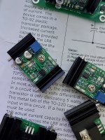
Today received the mainboard PCB’s. Just one hour mounting and see the result. Also updated post 1.


Attachments
Last edited:
Zoom777, no you can use them without problem.
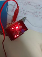
This evening tested the 12x 30mm positive regulator with succes.
This side soldered with hotplate.

This side soldered with hotair gun.

And then soldered T2 and board connector.


Later this week I build the negative regulator
This evening tested the 12x 30mm positive regulator with succes.
This side soldered with hotplate.
This side soldered with hotair gun.
And then soldered T2 and board connector.
Later this week I build the negative regulator
Last edited:
@Koifarm , thanks ... I got my first set of positive and negative boards working already. I don't have a hot plate , so I hand soldered the boards. Now waiting for the delivery of the reservoir caps for the main boards.
Attachments
I am wondering about this too. What are the changes needed to achieve eg. +/-5V?With this schematic about 6V, but you can modify the schematic for lower voltages.
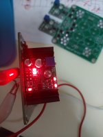
Tonight also tested the small 12x30mm neg.reg. with succes.
Gerber files also added to post 1.

Maybe next after some requests a through hole version size 25.4x 38.2mm fits also fisher heatsink.

Gerber files also added to post 1.
Maybe next after some requests a through hole version size 25.4x 38.2mm fits also fisher heatsink.
Attachments
Last edited:
How come you don't have stability issues with ceramic output caps? Usually these kind of regulators don't like small value low ESR capacitors at their output at all.
- Home
- Amplifiers
- Power Supplies
- An other LM78XX regulator