Measurements, no. Sims, yes.
Basically, when Mark suggested to add a ground loop resistor, I was also fixated on the "feedback to output gnd" rule, so I kept the feedback cap on the other side of the resistor. When he pointed out that there might be a problem with the way it was implemented, I re-ran the sims from Akitika to see how it worked. And indeed, if the feedback resistor is on the wrong side of the ground loop resistor, it doesn't work.
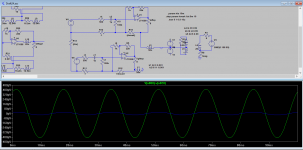
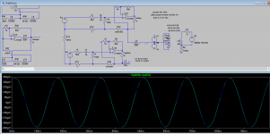
See the first two sims. The first one shows what happens when we increase the loop breaking resistor from 50m to 10r, with the input resistor and the feedback resistor attached. The hum at the speaker is strongly decreasing. Now, the second one shows what happens if the feedback is moved. No hum attenuation anymore.
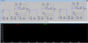
Then, I re-did the sim shown by Tom on the grounding page of the "taming the lm3886" serie. That's the third sim. It shows how the wrong grounding (not returning the input+feedback grounds to the load) impacts the accuracy of the feedback. Test1 and 3 show no error current going through the load, despite the insertion of the 10r ground loop breaker. Test 2 shows what happens with an incorrect sense point.
So that basically means that I have to join feedback and input to make the groundloop breaker working and that it shouldn't impact the distortion correction.
Basically, when Mark suggested to add a ground loop resistor, I was also fixated on the "feedback to output gnd" rule, so I kept the feedback cap on the other side of the resistor. When he pointed out that there might be a problem with the way it was implemented, I re-ran the sims from Akitika to see how it worked. And indeed, if the feedback resistor is on the wrong side of the ground loop resistor, it doesn't work.
See the first two sims. The first one shows what happens when we increase the loop breaking resistor from 50m to 10r, with the input resistor and the feedback resistor attached. The hum at the speaker is strongly decreasing. Now, the second one shows what happens if the feedback is moved. No hum attenuation anymore.
Then, I re-did the sim shown by Tom on the grounding page of the "taming the lm3886" serie. That's the third sim. It shows how the wrong grounding (not returning the input+feedback grounds to the load) impacts the accuracy of the feedback. Test1 and 3 show no error current going through the load, despite the insertion of the 10r ground loop breaker. Test 2 shows what happens with an incorrect sense point.
So that basically means that I have to join feedback and input to make the groundloop breaker working and that it shouldn't impact the distortion correction.
Attachments
Measurements, no. Sims, yes.
So that basically means that I have to join feedback and input to make the groundloop breaker working and that it shouldn't impact the distortion correction.
That makes sense, thanks!
I see now, I used this guy, GBU1007 is compatible with the Ohmite heatsink.
I found some other interesting diodes compatible with that heatsink. Either the GBU or the KBU package will fit. At mouser, we have two high amps diode bridges available, the 25A/400V KBU2504-G or the 15A/400 GBU15G.
Btw, that ohmite heatsink's footprint is identical to the 6390 serie from Aavid Thermalloy.
I considered going for a big metal bridge soldered under the pcb and heatsinked to the chassis but that turns into a precision mounting.
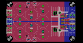
So here's a revision of the pcb board, allowing to use either that ohmite heatsink, the equivalent aavid or the more expensive "u" shaped aavid, for gbu or kbu bridges. Eagle files in the zip.
Attachments
I've sent the lm3886 files to smart proto. I should have the pcb on hand in one month or so...
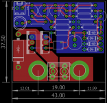
Meanwhile, I redid the dc-protect board. I didn't like the format. This pcb is made to be directly mounted on standard 19mm pitch speaker posts. It's also mono. Having one detector for stereo only saves a few resistors and cheap transistors, not really a big deal.
Meanwhile, I redid the dc-protect board. I didn't like the format. This pcb is made to be directly mounted on standard 19mm pitch speaker posts. It's also mono. Having one detector for stereo only saves a few resistors and cheap transistors, not really a big deal.
Attachments
Last edited:

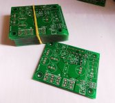
smartprototyping.com. I've used them for a while and never had a problem. I ordered 5 PS boards, 10 DC protection boards and 10 amp boards (enough for 5 stereo amps). Total cost with (slow) shipping was 35€ but that's because I placed two orders to stay under 22€ per order (the VAT and taxes exemption limit).
Now I need to upgrade my measurement setup to verify the design.
Now I need to upgrade my measurement setup to verify the design.
It shouldn't be too long now. Everything arrived.
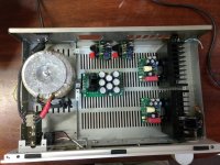
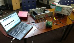
A quick mockup. I've still to tap the heatsinks, drill plenty of mounting holes and crimp a bunch of cables. And then on to the testing. Maybe some preliminary results next week.
Looking very nice! Great job. Is that a choke on input? Transformer from toroidy pl?
I just recycled the power section of an old build. Transformer is a 225va/2x21vac piece I found on ebay years ago. iirc, it's a velleman. As for the clamp on choke, I've no idea why it's on there to be true... it must be a leftover of the days I tried anything just for the sake of it.
It's alive. No particular problems at first sight but I've yet to properly test it. I'm clearly not aiming for a beauty contest here.
One or two layout errors to correct still. The most annoying one is that the spade connectors on the protection board are too close to the binding post holes. Nuts and washers risk to make contact if it's not carefully checked... that would defeat the whole point of the board.
I also think it would be best to move the gnd layer to the top for the PS, to avoid a problem if the heatsink scratches the solder mask (and, btw, I don't know why I ordered gigantic 62mm heatsink for the diode bridge).
Attachments

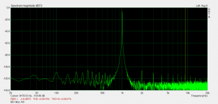
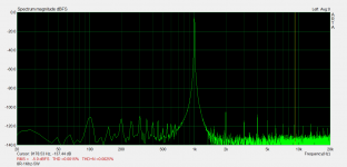
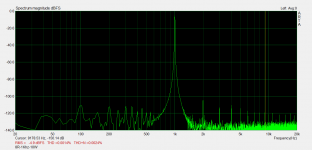
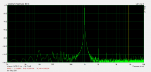
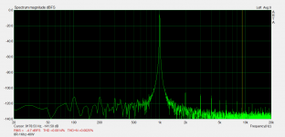
So, I promised measurements. Here are a few. The setup should be further tweaked: I've a groundloop that I cannot quite get rid of, due to the test setup. It's reduced by a strap from the output gnd of the amp to the rca gnd of the amp but not completely.
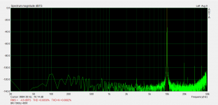
THD+N, at 8R, 1Khz, on a +/-30vdc supply (at idle):
1W: 0.0037%
5W: 0.0025%
10W: 0.0024%
20W: 0.0022%
40W: 0.0025%
I don't have the certainty given by an AP, measurements are made with a focusrite 18i8, an analog scope to set the power levels and a diy dummy load.
edit: those measurements include the DC protection board.
Attachments
Last edited:
Great job, LM3886 has a nice harmonic profile.
I wounder how would your board measure with regulated PSU.
I wounder how would your board measure with regulated PSU.
That is great outcome. No wonder lm3886 sounds great to me. I built about dozen so far, but still plenty chips in the drawer. My friends always need amplifiers, so I will build more.
Let us know if the boards are ready to order, I would buy some.
Congrats on job well done.
Let us know if the boards are ready to order, I would buy some.
Congrats on job well done.
Playing a bit around, a lot of the LF noise seems to be coming from the pot and input wires. Moving those around easily changes the thd+n at 1khz/1w from 0.008 to 0.004%. I'm going to try again one of these days, without the pot and with shielded leads.
Still, the board in itself seems ok. I also redid the tests with a 4R load, nothing special to mention.
The gerbers are attached and are also available on osh park. Please note that there is an extra .gko file in the zip which is the outline layer for osh park. I also attach the schematic and the board files for eagle. I've to check the BOM before posting it.
The dc protect board and the PS board need some small changes, I'll post them later on.
If someone is interested in prototyping a pair of boards, I will ship them for free (2 amps and PS), as long as he posts tests results and basic measurements. I've got three sets to offer.
Disclaimer: the gerbers are given for free, have been tested once but come without any warranty of any kind. Your build is under your responsibility.
Attachments
- Home
- Amplifiers
- Chip Amps
- An open source layout for LM3886?