Just got my board as well... adydula scared me into buying one before they run out 😀
As always, the quality on agdr stuff is amazing and this board is no different.
And I'm in the same boat as Turbon, have to finish current projects and then will circle back to this one; probably will build up late Feb. Looking forward to hearing this one and comparing to the others.
Till then, cheers!
Ha!!
Glad you got a board this will be a rare amp for sure!
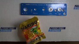
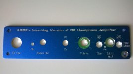
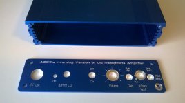
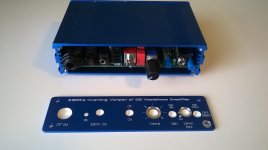
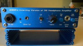
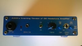
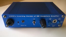
I got the panel from Front Panel Express today and its really very nice...makes the project complete!
The first one was funny in that in the box was a special "treat"!!! LOL.
Nice Touch Front Panel Express!
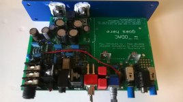
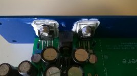
You can see the rear panel buffers without the heatsinks, no using the rear panel for the sink....
I also took the liberty to insert AGDR's name!!! After all he is the guy who did all the real work and made this one happen!!!
Alex
Glad you got a board this will be a rare amp for sure!
I got the panel from Front Panel Express today and its really very nice...makes the project complete!
The first one was funny in that in the box was a special "treat"!!! LOL.
Nice Touch Front Panel Express!
You can see the rear panel buffers without the heatsinks, no using the rear panel for the sink....
I also took the liberty to insert AGDR's name!!! After all he is the guy who did all the real work and made this one happen!!!
Alex
Attachments
-
 WP_20160126_002.jpg308.2 KB · Views: 251
 -
 WP_20160126_003.jpg317.1 KB · Views: 224
 -
 WP_20160126_004.jpg270.4 KB · Views: 228
 -
 WP_20160126_005.jpg277.9 KB · Views: 216
 -
 WP_20160126_009.jpg372.9 KB · Views: 128
 -
 WP_20160126_008.jpg343.6 KB · Views: 116
 -
 WP_20160126_007.jpg254.7 KB · Views: 95
 -
 WP_20160126_006.jpg279.3 KB · Views: 216
 -
 WP_20160126_010.jpg270.9 KB · Views: 106
 -
 WP_20160126_013.jpg288.8 KB · Views: 113
Thanks Turbon!
When I first listened to AGDR's prototype I was absolutely blown away at how good it sounded with T90's.
Since then I have had the chance to really listen and compare with the original O2, the ODA and my Crack OTL Tube Amp from Bottlehead.
The ODA still is a STELLAR amp and its as good as or even better than this version of inverting O2..but thats to my ears....
This new O2 version is very different to me, its exceptional to me in ways that are totally subjective. I find it a bit warmer than the other amps, by that I mean its less harsh, more smooth...maybe its the by-product of the design and eliminating some of the harmonics?
I with the O2 and ODA most always listen to music at the lowest gain setting. With this amp I am constantly using the higher gain to make it sound "great" to me ears. Almost like using the gain as a bass boost function.
The amp with great music is just marvelous. Its very smooth to me, very musical.
I have not seen the clipping indicator come on at all with the same music that I do see clipping with other amps....its almost like clipping with this amp is a thing of the past.
The only time I see the clipping light come on is during power on for a brief flash!
The thing that amazes me is that this few parts in this small box can produce such a wonderful sound......
Alex
Note: Its totally dead silent, just a silent black background wonderful in quiet passages ...makes for a great 3 dimensional sounstage with good music.
Ok AGDR whats next??? LOL!!
Hi guys! 🙂
Turbon & 4x4F150 - thanks for letting me know all the packages made it through OK! Hey when you get to the building don't forget that you need to revserse the two zener diodes D7 & D8 from the marking on the board, per post #51. Let me know if you run into any build problems. 🙂
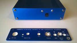
Alex - FPE did a great job there! Alex did his front panel with no color fill in the letting. Came out looking really good. Yeah FPE always includes that package of gummi bears. 😛
Alex shared his marking secret with me on his self-drilled rear panel. He puts a little bit of black paint on the face of the power jack and the end of the bolts for the TO-220s, then lines up the blank panel. That leaves marks right where the holes should be. I never thought of doing that! What a great idea. The result came out really well.
I'm glad you are enjoying the sound!! 😀
Turbon & 4x4F150 - thanks for letting me know all the packages made it through OK! Hey when you get to the building don't forget that you need to revserse the two zener diodes D7 & D8 from the marking on the board, per post #51. Let me know if you run into any build problems. 🙂
Alex - FPE did a great job there! Alex did his front panel with no color fill in the letting. Came out looking really good. Yeah FPE always includes that package of gummi bears. 😛
Alex shared his marking secret with me on his self-drilled rear panel. He puts a little bit of black paint on the face of the power jack and the end of the bolts for the TO-220s, then lines up the blank panel. That leaves marks right where the holes should be. I never thought of doing that! What a great idea. The result came out really well.
I'm glad you are enjoying the sound!! 😀
Ha!
I am setup presently downstairs at my kitchen table with a new HP Spectre 360 laptop I got as a unepected Xmas present. I have all my music library on a SSD and and using FOOBAR 2000 with an ODAC Rev A with the new amp.
My T90's are 250 ohms and I have an old set of Audio Technica M50's at 82 Ohms and have been using both back and forth, The obvious first thing I noticed is the T90's require more volume control turned up to make them play to my liking and the M50's are easily driven at a much lover level of volume...and these cans sound absolutely stellar with this amp / dac combo.
I have both plugged into the amp at the same time and the amp has no issues driving both well....amazing.
The front panel fitted very exactly the nut on the 3.5 m dac input has almost three threads to attach to...pretty good planning on the board layout there!!
Been playing for an hour, the case is hardly warm to the touch.
Now I am dreaming of getting another set of headphones!!! HA!!
Alex
Would you post the power calculations for the amp at the usual Impedances..ie 32, 150, 300, 600 etc..
Your great with the math and calculations!!!
Thanks
Alex
🙂
Your great with the math and calculations!!!
Thanks
Alex
🙂
Hi Alex! OK, but it will probably be later next week for the whole set. Several projects going on right now along with the day stuff. 🙂
But I'll do one right here, for 32R, to show the math.
The big thing to keep in mind with power calculations is the difference between peak voltages and currents vs. rms values. You need both with the power calculations. Peak values are the maximum current or voltage that will pass through a part, often the very top peak (or bottom peak) of a sine wave. rms numbers are the the "heating value" or "dc equivalent" of an ac waveform, which is the power delivery.
So lets start with the output current buffers. The BUF634 chips are good for 250mA max. So right there you have a "peak" value - the peak value of current can't exceed 250mA or the chip will current limit. In reality the current limit circuit isn't that precise, you can probably go a bit beyond 250mA, and then there is chip power dissipation to consider later. But for now lets say 250mA is the maximum output current.
At this point, before going any further with the load, lets do a check if the power supply can even supply that much current. There are two channels, of course, left and right. If a bit of music just happened to have the peaks of the sine waves on each channel at the same instant in time (and same polarity, both positive peaks), the maximum would be 2x 250mA = 500mA. To that add the quiescent (idle) current of all the chips and any circuit current. I'm going to just take a guess here rather than take time to add it all up. Lets say maximum quiescent is 50mA.
The total draw from the positive voltage regulator then (remember it was a positive music peak) would be 550mA. If the two peaks at that instant in time were the negative sine wave peak the current would flow through the negative voltage regulator.
Well the LT3015 is rated at 1.5A and the LT3080 at 1.1A (maximum = peak numbers here). The transformer I have specified in the BOM is 2.4A. Even when you take the charging spikes for the half waves supplies into account that transformer can still supply 550mA continuous. The voltage regulators are heat sinked to the rear panel. So the verdict here: the power supply can handle the 250mA peak current on each channel.
OK, back to the load. Assuming the 250mA peak current spike, that gives you an rms current of (0.707 * 250mA) = 177mA. For sine wave the factor of 0.707 gives you rms. For other waveforms the factor is different. Again, keep in mind here why we are changing from peak to rms. For the load *power* delivery we don't care about the peak current, we want the rms current.
The maximum load power delivery into 32 ohms is then the square of the rms current flow times the load impedance, sqr(177mA) * 32R = 1.0 watt. 😀
Some more double checks are in order to see if that number could actually be produced. Back to peak current for a minute. A peak current of 250mA through the 32R load would produce a load voltage of 0.25 * 32 = 8V. The power rails in the inverting O2 are +/-15.3V. From the BUF634 data sheet figure 14, for an output of 250mA, the maximum output voltage is around 10.5V for either rail swing with supplies of +/-15Vdc. So sure enough, the output current buffers would be able to source the 8V peak voltage swing to the load for the 250mA peak current. Check. 🙂
Next up is the power dissipated by the buffer chip. This one is a little tricky in that it is the power caused by the quiescent current along with the power dissipated by sourcing (or sinking) the load current. It is easy to forget that quiescent current contribution. The queiscent current will be around 10mA for the 100R bandwidth control resistor being used, from figure 9 in the BUF 634 data sheet. To figure quuiescent power you have to use BOTH power rails - folks forget that! So 2 * 15.3V * 10mA = 306mA. Note there is no peak vs. rms here since the quiescent is a DC value already.
For the power dissipation due to the load current, we switch back to rms values because we want the power with sine waves being delivered to the load. The voltage across each current buffer at the 250A peak (177mA rms current) is the power rail minus the rms voltage being supplied: (15.3Vdc - (0.707 * 8V)) = 9.6W PLUS that 0.3mW of quiescent power = 9.9W. Hmmm... this one requires some thought. The buffer chips are heat sinked, but not to the case, to finned heatsinks. And they are inside the case. I'll look up the thermal numbers for those heatsinks but I have a pretty good idea right now that 9.9W of dissipation isn't going to happen for that (small) size heatsink in an enclosed environment (although it is an aluminum case, a plus for thermal dissipation). If the BUF634s were heatsinked directly to the case, like the voltage regulators, they probably could dissipate that much power.
BUT... like most things... nothing is simple. 😀 This is where that magic difference between the power dissipation with constant sine wave testing vs. the power dissipated by actual music comes in. With real music amplitudes bouncing around, the average (voltage) level for music tends to be about 1/3 or so for pure sine waves. And power is a square law, so it drops fast with a linear decrease in voltage. If we were to go back through all the math for real music I'll take an educated guess that the power dissipated by the buffer chips would drop to somewhere around 2.5W max or so each (still with 250mA absolute maximum peaks in the music), which should be workable with those finned heatsinks inside the case.
This last item is why you have to be very careful when someone is saying an audio project/product is overheating when testing with pure sine waves. That doesn't apply to real life audio usage. NwAvGuy even said as much in his blog, that the O2 will fry in a certain number of minutes with pure sine wave testing unless allowed to cool occasionally during the testing. That applies to testing the O2 Booster Board project, too. 😉
Lol! How about that for a long winded answer? 🙂
Last edited:
and now I know why I asked YOU to explain this!!! Ha!
and as usual you have done a wonderfully detailed explanation that helps us understand the simple but complex relationships that are entailed with these circuits...
Thanks Much for the details!!
Looking forward for the other impedances.....work first!!
Alex
and as usual you have done a wonderfully detailed explanation that helps us understand the simple but complex relationships that are entailed with these circuits...
Thanks Much for the details!!
Looking forward for the other impedances.....work first!!
Alex
Last edited:
My buffer dissipation calculation is wrong!
Alex - thanks for asking the power delivery question!
In the shower last night it hit me that the BUF634 power dissipation calculation in my post above in the last 3 paragraphs couldn't possibly be correct. The result says each chip is dissipating 10W to deliver just 1W to the load, with +/-15.3Vdc rails. 😛 I did that post in a coffee shop and was having a phone conversation at the same time. 😱
The error is that the power dissipated by the output chips is the rms voltage across the chip times the rms current through it. Take a look at my calculation in the 3rd from the last paragraph, the units don't even match up. I calculated the rms voltage across the chip for peak 250mA current delivery to the load, but then called that wattage. I had left multiplying by the load current out. The train jumped the tracks from there.
It should be:
(power rail - (rms load voltage during the 250mA peak current delivery to the load)) * rms current through the load (and therefore through the buffer chip)
(15.3V - (8V * 0.707)) * (250mA * 0.707) = 1.7W
plus the 300mA of quiescent current. The grand total of each buffer chip power dissipation is:
1.7W + 0.3W = 2W (per buffer chip, one for each channel)
The good news is that 2W per buffer chip with the finned heat sinks should be just fine, even with continuous sine wave testing, which is what this result would apply to. What I wrote above about actual music power dissipation being less still applies of course. Real music, rather than continuous test sine waves, with 250mA absolute maximum peaks would likely result in buffer power dissipation of something like 0.75W - 1.5W. Depends on the average level and number of peaks of the particular music involved.
Last edited:
I have spent the past two days ABing the O2, the inverting o2 and the Crack…over and over, using a 1Khz test tone to set up the SPL identical.
The original O2 and the inverting O2 I cant tell apart with any objectiveness!!
The Crack and the O2 inverting I can to a fair degree!!
The Crack has a different soundstage, and is not a clear as the Inverting O2.
The Inverting O2 is definitely clearer, less muddy on the low end, bass and mid -bass
Its like the Crack has some bass boost cranked in on the lower end….
Both sound wonderful but the inverting o2 wins out in clarity and articulation….
Who knows why, but I would prefer the inverting O2 to the Crack at the moment!!!
Its like I can hear more cleanly whats being presented…
Just using the 250 ohm T90’s trying not to cloud things up more with more headphones!
The Inverting O2 seems so much more crisp. Clear and transparent it still that musicality to me as well….
The Crack seems very “warm” now to me…
Depending on the material the Crack can present a very pleasing presentation…..
So I now go back and forth with the same material and enjoy both presentations!!!
So much Fun!
Alex
Note: The new inverting O2 with its higher rails can easily drive these 250 ohm T90s to painfully loud levels, way too loud for safe listening. I used a homemade adapter and a radio shack SPL meter to set the volume to 80 db or so with a 1Khz test tone readily available on the net. Using the same dac so Windows doesnt have to re-enumerate the dac and add to switching time I can go between amps in 10-15 seconds.
Last edited:
That's the expected result for non-negligible amounts of 2nd-order intermodulation distortion, actually (of which in turn I'd expect a simple OTL amp to have a fair amount, invariably linked to its 2nd-order harmonic distortion). The (f1-f2) components it generates muddle up the low end. The effect can be pleasing on sparse material but tends to fall flat once things get more busy.The Crack has a different soundstage, and is not a clear as the Inverting O2.
The Inverting O2 is definitely clearer, less muddy on the low end, bass and mid -bass
Its like the Crack has some bass boost cranked in on the lower end….
T-network to reduce inverting feedback resistor values
Alex - very interesting what sgrossklass posted! You have pretty good ears to pick that up. 🙂
Unfortunately I'm not going to be able to post the rest of those maximum output powers anytime soon. I have a bunch of business stuff going on suddenly not related to the audio hobby that is sucking up a lot of time. But as per our email exchange a couple of days ago, for 250R cans like the T90 the limitation, if any, will be voltage and not current. The maximum votlage swing of the the inverting O2 is 2x what is needed for 120dB SPL out of the T90. Some other high Z cans might be much lower sensitivity and need a higher votlage swing, but hey at least this amp has 3V more maximum swing than NwAvGuy's O2 due to the +/-15.3V power rails.
Also something unrelated I've been meaning to post. I bought this book on analog filters a couple of weeks ago
http://www.amazon.com/Analog-Filter-Circuit-Design-Handbook/dp/0071816712 (ISBN-13 978-0071816717 in case the link eventually goes away)
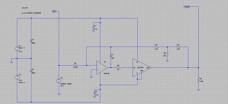
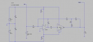
and in there on page 517 he has a couple of really good ideas related to inverting op amp configurations. One is to use a "T" network in place of the feedback resistor to dramatically reduce the value and the associated Johnson noise. The 33K feedback resistor in the inverting O2 output stage could be replaced with two 3.3K in series, with a 422R resistor to ground in the middle, as in the attachments below.
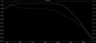
The one problem that creates is messing up zeroing out the DC output offset. The output DC gets divided by that 422/3300 divider and the loop DC correction would get scaled down by that much. A solution is to put a capacitor in series with the 422R to ground, so the feedback voltage divider only applies to the AC signal. But that requires a fairly large cap as the plot shows, 20uF or so, 4x 4.7uF film caps in parallel. The capacitor in the feedback loop will probably slow down the rate of response of the DC correction loop, but it really shouldn't make any real-world difference. The steady-state result will be the same.
Another neat trick in the book is drastically increasing the input impedance of the inverting amp by using a second inverting stage and feeding the output back to the input of the first one via a resistor. The currents at the input node all sum, with most of the input current to the first inverting stage now supplied by the feedback amp. If *all* the current is supplied it becomes an oscillator, as he notes, so the resistor values are adjusted such that the source still supplies 10% or so.
I don't have any plans to do any more board turns of the inverting O2 to add any of this stuff. I just wanted to post the ideas in case someone else should be reading this some day and decide to build their own DIY inverting amp. 🙂
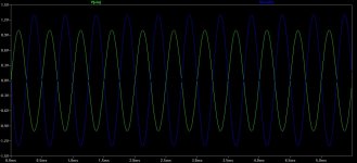
Note that in the transient plot below with the T network that the output (blue) is still 1.3x voltage gain, same as the orginal 33K/24.9K values with the 33K resistor in place the the T network. The ouput is inverted because it is an inverting stage, of course. The first schematic and two plots are with the 422R "T" resistor directly grounded. The second print and plot are with the 20uF series DC blocking cap added to the 422R.
Alex - very interesting what sgrossklass posted! You have pretty good ears to pick that up. 🙂
Unfortunately I'm not going to be able to post the rest of those maximum output powers anytime soon. I have a bunch of business stuff going on suddenly not related to the audio hobby that is sucking up a lot of time. But as per our email exchange a couple of days ago, for 250R cans like the T90 the limitation, if any, will be voltage and not current. The maximum votlage swing of the the inverting O2 is 2x what is needed for 120dB SPL out of the T90. Some other high Z cans might be much lower sensitivity and need a higher votlage swing, but hey at least this amp has 3V more maximum swing than NwAvGuy's O2 due to the +/-15.3V power rails.
Also something unrelated I've been meaning to post. I bought this book on analog filters a couple of weeks ago
http://www.amazon.com/Analog-Filter-Circuit-Design-Handbook/dp/0071816712 (ISBN-13 978-0071816717 in case the link eventually goes away)
and in there on page 517 he has a couple of really good ideas related to inverting op amp configurations. One is to use a "T" network in place of the feedback resistor to dramatically reduce the value and the associated Johnson noise. The 33K feedback resistor in the inverting O2 output stage could be replaced with two 3.3K in series, with a 422R resistor to ground in the middle, as in the attachments below.
The one problem that creates is messing up zeroing out the DC output offset. The output DC gets divided by that 422/3300 divider and the loop DC correction would get scaled down by that much. A solution is to put a capacitor in series with the 422R to ground, so the feedback voltage divider only applies to the AC signal. But that requires a fairly large cap as the plot shows, 20uF or so, 4x 4.7uF film caps in parallel. The capacitor in the feedback loop will probably slow down the rate of response of the DC correction loop, but it really shouldn't make any real-world difference. The steady-state result will be the same.
Another neat trick in the book is drastically increasing the input impedance of the inverting amp by using a second inverting stage and feeding the output back to the input of the first one via a resistor. The currents at the input node all sum, with most of the input current to the first inverting stage now supplied by the feedback amp. If *all* the current is supplied it becomes an oscillator, as he notes, so the resistor values are adjusted such that the source still supplies 10% or so.
I don't have any plans to do any more board turns of the inverting O2 to add any of this stuff. I just wanted to post the ideas in case someone else should be reading this some day and decide to build their own DIY inverting amp. 🙂
Note that in the transient plot below with the T network that the output (blue) is still 1.3x voltage gain, same as the orginal 33K/24.9K values with the 33K resistor in place the the T network. The ouput is inverted because it is an inverting stage, of course. The first schematic and two plots are with the 422R "T" resistor directly grounded. The second print and plot are with the 20uF series DC blocking cap added to the 422R.
Attachments

Last edited:
Usually using a "T" network in a feedback loop is a bad idea, unless you really need it and you know what you are trading it for. Just convert it into an equivalent "D" network to see what it does.
Thanks for the information....so the real world has gotten in your way of this hobby!! Ha!
When I was working for IBM for 32 years it happened to me many times.....
Just don't go pull a disappearing act! Like NWAVGuy!!
As far as my ears are concerned. I being 66 years old dont have the hearing of a 20 year old for sure, but I have been blessed with good hearing even now!! I keep wondering how long this will go on....I guess I dont listen like most people. I listen for things that most folks have no clue as to why or how come!
My wife and sons think I am nuts most of the time!! Listening for things like musicality, timbre, transparency, and all those subjective things are difficult and depending on the time of day, mood and amount of beer consumed have effects on these.
But over time and using controlled conditions I can get a farily good idea on how something sounds and make some fairly and often painful decisions and comments.
When we build an amp or device and turn it on for the first time, its a usually wonderful experience, and then over time the worts may or may not come out!
Its easy to be swayed by how many pounds a piece of equipment weighs, the thinkness of the aluminum in the case, or is the perf board solid copper! Things that are neat to some, but may not have one iota of affect on the sound.
Having well recorded and well mastered material, setting the listening levels with a SPL meter, listening to a short piece of well known material, being able to switch quickly between setups, changing only one thing at a time, having a partner in crime to help do A/B switching...all help to sore out how things sound.
When I decided to get back into this hobby, I was very curious how this area of audio had advanced. Seeing folks still opining on vacuum tubes, cables, noise filters etc...not much has changed. Things are smaller, THD and specs have gone down into the inaudible range.
Then the O2 came out with the design goals, to me seemed laudable. Making a device or amp using the least amount of parts, arranged in a way to produce an amp that basically would be transparent, ie no effect on the signal input, a design that had parts arranged in a way that allowed this to happen and then back it up with objective measurements. A good approximation of a straight wire with gain!! What many of us have been looking for since the beginning of the sine wave!! Ha!
Then we could take that device and be in audio nirvana!! Ha! Well that story has take many twists!! Good and not so good...
But the neat thing in this diatribe is AGDR has taken up the mantle since the disappearance of NWAVGuy and birthed many updates and changes to amps like but very different to the O2.
Please keep up the ideas!!
Alex
"My wife and sons think I am nuts most of the time!!" - The prize we have to pay as husbands, fathers and audiophiles... 😀
Regards
Regards
Usually using a "T" network in a feedback loop is a bad idea, unless you really need it and you know what you are trading it for. Just convert it into an equivalent "D" network to see what it does.
Thanks for the tip! I know you have done a lot of work and measurements with feedback networks.
Using the transformation equations here
Pi and T networks
I come up with 32.4K for the series resistor and 4.1K for the two legs to ground of the delta. Simulates just fine, but 32.4K would be about the same Johnson noise as the original single series 33K. Please tell me more about the "T" networks! What sort of problems have you run into with those?
Thank you for the feedback! 🙂
BTW - I have 100% of the parts for your "crocodile" headamp accumulated here now, even those special order coils, just haven't soldered it together yet. I will definitely do that as time permits. I'm eager to give it a listen.
Last edited:
... all those subjective things are difficult and depending on the time of day, mood and amount of beer consumed have effects on these.
I'll second that motion with a pint! 😀

You have done an excellent job evaluating (and building!) all the different amps. That takes a lot of effort (a patient family!!) and a good set of ears. Keep up the great work! 🙂
If you have a look on those two resistors of delta which connected to ground closer. One does nothing but loads the output. The other one, which is connected to the inverting input, will decrease your feedback loop gain and increase noise gain. So at the output you will have more distortion and noise compare a single resistor. ~33k is not too large or fancy value to avoid it.
Last edited:
- Status
- Not open for further replies.
- Home
- Amplifiers
- Headphone Systems
- An inverting version of the NwAvGuy O2 headphone amp vs. the original: THD+N