Slot vents in themselves are fine.
Damping in an MLTL should not significantly attenuate overall SPLs, nor shift the box gain away from what is intended. If it does, then it's not been designed properly. A well designed cabinet of this kind should not have any issues with harmonic modes.
Damping in an MLTL should not significantly attenuate overall SPLs, nor shift the box gain away from what is intended. If it does, then it's not been designed properly. A well designed cabinet of this kind should not have any issues with harmonic modes.
I seen a topic that I have not seen discussed. That is, the interference nulls created with transmission line type speakers.
As in pipe harmonic modes? It's mentioned in one way or another in just about every QW thread on the forum. 😕
As in pipe harmonic modes?
No, in fact the frequency(s) are exactly between harmonics. If you take a transmission line with a driver at zero position (not offset) a null in the far field occurs at 4 times fundamental (between third and fifth harmonic). This wavelength is the length of the pipe, the pressure wave coming from the vent is 180 out of phase with speaker front wave. If you offset the driver (1/4 wavelength of this frequency from the closed end) the vent pressure sums now to zero at that frequency because you now have two separate pressure waves adding inside the pipe. Therefore, there is no pressure wave coming from the vent to cancel the front wave pressure at that frequency. This nulling occurs at all multiples of this wavelength, but the first (or lowest) is the most serious.
Here's another way this nulling effect could be mitigated: mount a second driver separated by the distance equal to 1/2 wavelength of the frequency to be eliminated (measured inside the pipe), and the internal pressure wave then sums to zero at the vent terminus for that frequency.
The nulling effect is part of the same issue as the peaks with the same solutions. Take the peaks away the valleys go with.
dave
dave
There's gotta be a better way to fix the dip, right?
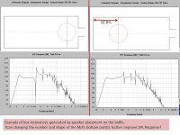
Attached HornResp data comparing SPL response when the speaker is located near bottom of box, and ~32.8% down from top of a quater wave long box. The selection of stuffing material can also shape SPL response and final sonics. Naturally, not all designs permit flexible speaker location options.
What is the best simulator to add port shape modeling?
?Exporting the HornResp model into AkAbak and then extending that AkAbak model to include detailed port models?
Has anyone successfully modeled multiple ports with X,Y,Z dimensions that control resonance and air flow restriction?
Attachments
Last edited:
Attached HornResp data comparing SPL response when the speaker is located near bottom of box, and ~32.8% down from top of a quater wave long box. The selection of stuffing material can also shape SPL response and final sonics. Naturally, not all designs permit flexible speaker location options.
What is the best simulator to add port shape modeling?
?Exporting the HornResp model into AkAbak and then extending that AkAbak model to include detailed port models?
Has anyone successfully modeled multiple ports with X,Y,Z dimensions that control resonance and air flow restriction?
I have successfully modeled port shapes by approximating a 2 dim port as a series rectangular ports of prescribed dimensions. This is how I modeled the Karlson aperture. See post in the Karlson thread here: http://www.diyaudio.com/forums/full-range/213594-karlson-10.html#post3528706 I have also modeled arbitrary ports located at different points along the TL to detune the Q of certain cavity resonance modes. See my thread here: http://www.diyaudio.com/forums/full-range/237384-flute-pipe-tl.html.
Akabak is very flexible and allows arbitrary xyz (and alpha, theta, phi angular orientation) placement of ports/vents/radiators.
Hi,
Then Bud Fried came along with a load of unverified nonsense,
but he made it sound good, which it isn't, and was very influential.
rgds, sreten.
Can you please state which exact Bud Fried T-line speaker models you have heard?
Hi,
I cant say I completely understand all the technical issues. But my first speaker build I plan on being a T.L.
I'm I right in saying, that you are describing the same technique used in PMC speakers, with this back pipe?
http://www.tnt-audio.com/jpg/pmc_peter.jpg
http://www.6moons.com/audioreviews/pmc4/02.jpg
http://www.positive-feedback.com/Issue48/images/pmccut.jpg
I hope not. It's all one line (or it should be) -the driver just happens to be offset / tapped into it a x distance from the throat. 99.9% of the time, it should be offset for the most balanced response (there are exceptions). None of this is new, it's been done for years. Augspurger, King et al all go into detail & there's a wealth of information & quality designs out there for all kinds of QW lines, be they straight or tapered TLs, MLTLs, or whatever & the vast majority have the driver offset. TBH, I'm startled the OP hadn't noticed since it's rare nowadays to find a properly designed QW / TL where the driver is not offset.
Or more precisely: at a frequency whose wavelength is equal to the TL line.we see the dip is occurring at a frequency that's equal to the length of the transmission line.
I would also imagine most folks have seen TL driver offset, but I wonder how many know why it is used. I think most would say that it effects harmonic modes. But, I think that less folks know that it also effects destructive interference. And, that is what the OP was referring to.
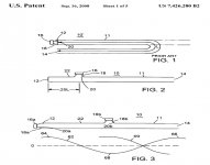
Fig.2 refers to what the OP was talking about. Fig.3 is what I referred to in post #25
Regards,
Coch
Attachments
I would also imagine most folks have seen TL driver offset, but I wonder how many know why it is used. I think most would say that it effects harmonic modes. But, I think that less folks know that it also effects destructive interference. And, that is what the OP was referring to.
I would think that this is well understood by anyone who has heard of Augspurger and King.
Bob
Well it is very basic stuff. I knew about the effect as a young man working for an antenna inventor, we called it the 1/4 wave stub filter.
1-wavelength waveguide cancellation
Hello Patrick,
You seemed to stop short in this thread. Did you pursue your transmission line or quarter wave pipe with the offset solution to the 1-wL cancellation? Any actual results?
I believe that the total line length, including your "stub" sets the quarter wave line length, so the "stub" length is not wasted, but part of the total. The driver is just moved up the waveguide by approximately a quarter of the length.
Curious if you realized positive results, or stopped the thread due to a lack of success.
All the best,
- James
Interesting!
Like most people do, I typically take a 'trial and error' approach to hornresp, and generally optimize for flat low frequency response.
The thing that was intriguing about the Acoustimass is that the woofer offset is quite large!
Here's a clone of a TH-Mini tapped horn, along with the Acoustimass; the TH-Mini has nearly zero offset.
Interestingly, it appears that the TH-Spud uses a lot of offset, along with a slow taper, similar to the acoustimass. I'll have to run some sims on the TH-Spud and see if that offset is tuned to the first dip. Perhaps that explains why the TH-Spud has relatively low efficiency, but wide bandwidth? Whereas the TH-Mini has high efficiency and *low* bandwidth?
(Just thinking out loud here.)
Hello Patrick,
You seemed to stop short in this thread. Did you pursue your transmission line or quarter wave pipe with the offset solution to the 1-wL cancellation? Any actual results?
I believe that the total line length, including your "stub" sets the quarter wave line length, so the "stub" length is not wasted, but part of the total. The driver is just moved up the waveguide by approximately a quarter of the length.
Curious if you realized positive results, or stopped the thread due to a lack of success.
All the best,
- James
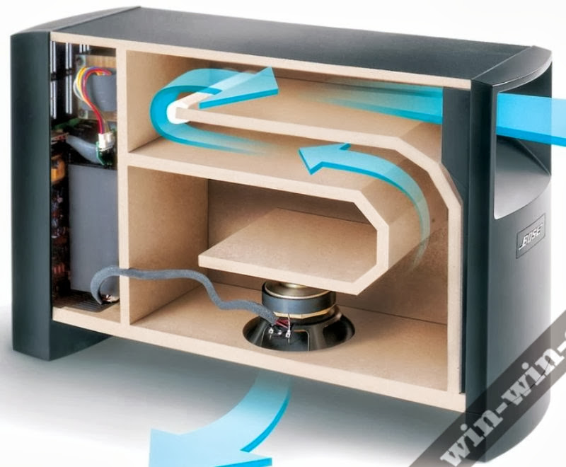
For the most part I was just exploring how Bose did it.
Considering that they sold bandpass boxes for many years, I found it interesting that they switched to transmission lines, so I was curious to learn why.
At the moment I am running the following arsenal of subs:
At home I have three subs. One is vented, on is a tapped horn, one is bandpass. All are distributed a la Geddes.
In my car everything is horn loaded. The sub is a front loaded horn.
The threads related to these projects are http://www.diyaudio.com/forums/subwoofers/192539-tapped-horn-lazy-impatient.html , Car Audio | DiyMobileAudio.com | Car Stereo Forum - View Single Post - Sealed Box versus Infinite Baffle
The car sub is particularly effective. It's a horn built into a sonotube. Picture a horn sliced up into pieces like slices of pie, and you get the general idea. Works very well. The horn is huge, something like six cubic feet, but it weighs less than 40lbs. The use of sonotube allows for a sub that's light enough to remove from the car when necessary, but is still strong and rigid. Recommended!
Even if I don't like to be considered a friend of MJK, I have to completely agree with Bob Brines.
Even if the MJK mathematics and physics could be largely improved (using that "academic" knowledge that he carefully dislikes -private communication), the calculations provided by his Mathcad sheets are far more predictive than the majority of the models (unfortunately) still in use.
Let me guess that a better handling of the WHE or the equations governing the stuffing could improve his calculations by a 20%. Let me say that his 80% accuracy is "good enough".
Quite. Martin's got the pipe physics down. Hardly surprising given what he does for a living. Damping is more of a variable & I'm not sure there's much he can do about that. There's a baseline for hollow-fibre material which he used -fine of course & flexible enough for most conditions. But the fine details vary with the type of that (not all created equal, or intended to be so), and shift somewhat more if other materials are used also. Still good enough though, especially if you've done some testing of your own & can adjust for those differences.
- Home
- Loudspeakers
- Full Range
- An Improved Transmission Line Alignment