Hypoteses non Fingo
True.
But there are a lot of models (made by the "academics") widely used in the acoustic industry.
Me, I have checked some of them.
The most widely used is the Delany-Bazley (and his variations). See The Delany-Bazley model for the polyester fiber.
Another variation is the one made by Komatzu (I have checked also this one, but I haven't "published" the results).
Miki and Komatzu have the advantage of being causal.
MJK doesn't care.
Why should he? It works well enough for the vast majority of purposes, which is ultimately what counts & what he was after. Good enough is good enough. Perfect is a pain in the proverbial, and rarely worth the considerable extra effort involved (typically an exponential curve). This is especially the case when you consider that there are a large number of different variations of materials out there. Not all Dacron is the same, nor do other materials possess exactly the same behaviour. You can add variability of the individual circumstances -exact weights, locations &c. into that also.
Martin isn't against theory. But he does prefer it if the theorists actually do some experimenting themselves. It generally helps their work. The converse is also true.
Martin isn't against theory. But he does prefer it if the theorists actually do some experimenting themselves. It generally helps their work. The converse is also true.
I'm not discussing the quality of the MJK work (good enough, I repeat), I'm saying that dealing with fiber filling is not "black magic".
I put the microphone inside the transmission line at various resonance frequency, and move along the length of TL-line to measure what happen inside it. I can found that the "Peak" and "Dip" SPL are found along the TL-line wave-length 1/4, 1/2, 3/4....).
So, is it possible to use this method to determine the exact Driver-offset location (i.e. 1/4 or 1/3 )?😕
So, is it possible to use this method to determine the exact Driver-offset location (i.e. 1/4 or 1/3 )?😕
Not 'exact' due to the impact of damping and taper on a TL's effective acoustical path-length, though at odd harmonics of its physical path-length is plenty close enough IME as well as many others.
Even tapering up to a 10x change doesn't affect it much according to MJK's math/actual measurements, from ~1/3 to 2/5ths [scroll down to pg. 12, TABLE 4]: http://www.quarter-wave.com/TLs/Alignment_Tables.pdf
GM
Even tapering up to a 10x change doesn't affect it much according to MJK's math/actual measurements, from ~1/3 to 2/5ths [scroll down to pg. 12, TABLE 4]: http://www.quarter-wave.com/TLs/Alignment_Tables.pdf
GM
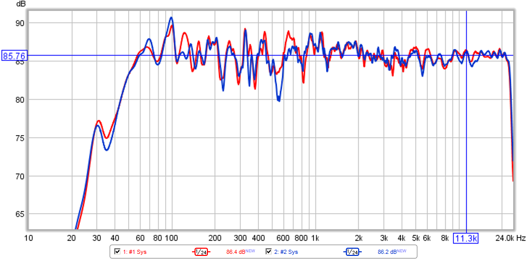
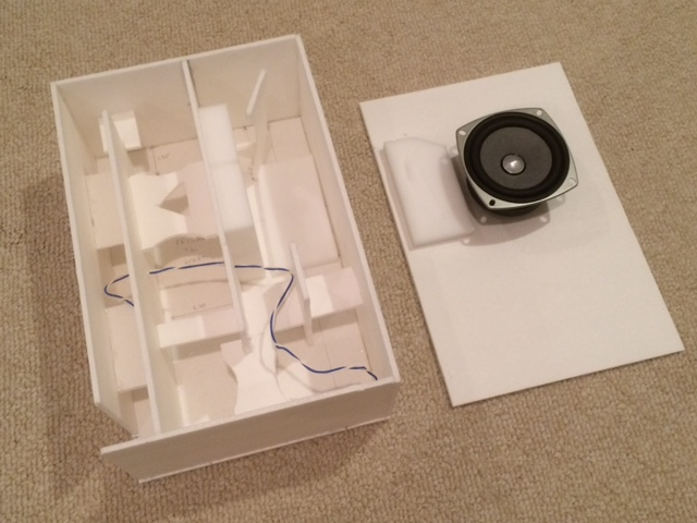
This is my first time posting, but I've been lurking here for some time now sponging up new information. I had to come back here to post this... I was experimenting with transmission lines for a while but found there was not much frequency range before that first big harmonic dip in the response. I tried moving the driver 1/3 down the path and it worked perfectly. I used this method for my car subwoofer and modelled it in hornresp
I was so happy with this it worked on the first attempt. I have no measuring equipment yet, but from what I could hear it was so much tighter (like a sealed box) except a flat response down to 24hz. I had this crossed over to my car speakers at 100hz and compared to the previous vented box I had with the same woofer I had nice mid-bass back. This is like having the best of a sealed and ported box at the expense of its size
I was so happy with this it worked on the first attempt. I have no measuring equipment yet, but from what I could hear it was so much tighter (like a sealed box) except a flat response down to 24hz. I had this crossed over to my car speakers at 100hz and compared to the previous vented box I had with the same woofer I had nice mid-bass back. This is like having the best of a sealed and ported box at the expense of its size
Attachments

This is my first time posting, but I've been lurking here for some time now sponging up new information. I had to come back here to post this... I was experimenting with transmission lines for a while but found there was not much frequency range before that first big harmonic dip in the response. I tried moving the driver 1/3 down the path and it worked perfectly. I used this method for my car subwoofer and modelled it in hornresp
I was so happy with this it worked on the first attempt. I have no measuring equipment yet, but from what I could hear it was so much tighter (like a sealed box) except a flat response down to 24hz. I had this crossed over to my car speakers at 100hz and compared to the previous vented box I had with the same woofer I had nice mid-bass back. This is like having the best of a sealed and ported box at the expense of its size
Nice work! I agree that TL's can make some incredible tight bass. I did some thing similar with a much smaller woofer and got as you say, the tight response of a sealed but extension of a bass reflex. It requires damping/stuffing along the line to make the two impedance peaks merge and become one squashed bump. That is the point it becomes a periodic and is best trade off for low group delay and bass extension. The model and build agreed pretty well.
More info here.
http://www.diyaudio.com/forums/multi-way/281778-low-cost-pmc-inspired-tl-monitor-dc130a-dc28f.html
Can you please state which exact Bud Fried
T-line speaker models you have heard?
Hi,
The idea that you need to have heard a speaker to have
any opinion of its technical merits is entirely ridiculous.
Fact is B.F.'s claims for his speakers go way beyond
verifiable, and are largely invented marketing bluster.
rgds, sreten.
I still (after all this time) can't wrap my head around the fact that the issues that the OP originally posted were not addressed ??? 
Except by me...
Except by me...
Thank you for the reminder. I will look up those patents. I know Bose gets a lot of flak on audio forums, but they've invested in some interesting research over the years.
Patent US7426280 - Electroacoustic waveguide transducing - Google Patents
Interesting. It looks like a second driver is placed in the transmission line, at a distance where it will 'fill in' the null that would typically appear.
As a bonus, I imagine the second driver would also assignment the low frequencies.
Interesting. It looks like a second driver is placed in the transmission line, at a distance where it will 'fill in' the null that would typically appear.
As a bonus, I imagine the second driver would also assignment the low frequencies.
BTW this could be modeled in akabak or hornresp. And it would work for BLHs and tapped horns too.
The Bose design is just an offset TL with taper - not sure what is novel that can be claimed on a patent.
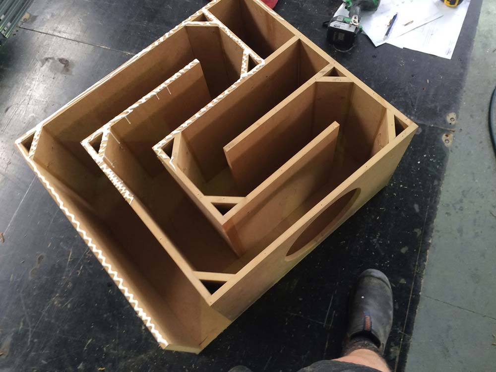
Their design:
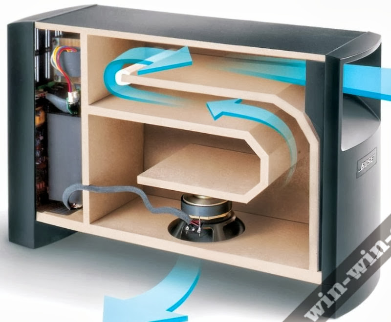
Is actually similar to a very large PMC TL without the stuffing:

And my implementation with a small 5.25in woofer and lots of stuffing to get a smooth roll off and low group delay:
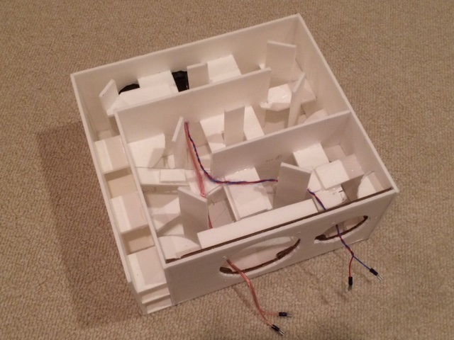
This thing makes an impressive amount of clean bass for its size. It feels like an 8in woofer in sound quality.
It also has very cone motion control as I am able to play some tracks with known heavy handed bass lines and it doesn't crap out.
Related to this is a 3:2:1 taper TL I made for the FF105WK 4in driver and when stuffing is used only in the portion from closed end to driver, the bass pulse is impressive.
Here is video of bass air pulse from 82dB SPL music being played.
Change .asc to .mov to watch:
http://www.diyaudio.com/forums/atta...ookshelf-ff105wk-tl-vent-action-movie.mov.asc
Their design:
Is actually similar to a very large PMC TL without the stuffing:
And my implementation with a small 5.25in woofer and lots of stuffing to get a smooth roll off and low group delay:
This thing makes an impressive amount of clean bass for its size. It feels like an 8in woofer in sound quality.
It also has very cone motion control as I am able to play some tracks with known heavy handed bass lines and it doesn't crap out.
Related to this is a 3:2:1 taper TL I made for the FF105WK 4in driver and when stuffing is used only in the portion from closed end to driver, the bass pulse is impressive.
Here is video of bass air pulse from 82dB SPL music being played.
Change .asc to .mov to watch:
http://www.diyaudio.com/forums/atta...ookshelf-ff105wk-tl-vent-action-movie.mov.asc
Last edited:
See also 2.3 fig. 5 in the Aj-horn introduction manualPatent US7426280 - Electroacoustic waveguide transducing - Google Patents
Interesting. It looks like a second driver is placed in the transmission line, at a distance where it will 'fill in' the null that would typically appear.
As a bonus, I imagine the second driver would also assignment the low frequencies.
AJHorn manual
@xrk - the patent referenced by @cochleus is from 2008. It features an additional woofer to smooth out the null.
I still (after all this time) can't wrap my head around the fact that the issues that the OP originally posted were not addressed ???
Except by me...
??? I didn't follow this thread originally, just popped in one time and now, but in a quick read, the issue was dealing with odd harmonic dips in resonant pipes and the various ways it's been done including adding an extra offset driver [tapped or not] like I suggested for dealing with them in a BIB, though now that I think about it was probably back on one of the long gone 'Full-Range' forum threads; so what did I miss that you're referring to?
WRT Hiraga's MLTL, my interpretation based on experience is that it's basically a multiple tuned pipe [mass loaded], inverse tapered TL, which I've recommended on various occasions [though with a simple duct vent tacked onto its terminus] and posted a sketch of one I built long ago for a RadioShack 'FR' driver, though AFAIK the person that wanted it decided he was happy enough with it on the OB he used to break it in, so never been critiqued on any forum.
The only thing not clear to me is whether or not the variable damping is strictly in the vents and/or used to create the taper; with the latter being my SWAG since I've used it to fine tune [selectively re-taper] [ML]TLs by ear/basic measurements back before computer aided design reduced it to maybe having to adjust its stuffing density.
GM
odd harmonic dips in resonant pipes
Nope. The freq. in question is not a pipe harmonic. The wave length is equal to the line length.
- Home
- Loudspeakers
- Full Range
- An Improved Transmission Line Alignment