Nice to see it is up and running. Good luck, looking forward to hearing your impressions 🙂Certainly. Thank you.
I appreciate your helps. I already tested it with lower bias settings before it started blowing fuses. It sure was impressive. Looking forward to re-start adjustment and equalizing channels when the ordered fuses arrive.
Were you blowing fuses during adjustments or at power up/down cycles? I don't remember the configuration of your power supply. Are you using some soft start , say a CL60 thermistor?
Given your higher transformer rating, I agreed with the suggestions of trying higher rated fuses.
Good luck with your build.
Given your higher transformer rating, I agreed with the suggestions of trying higher rated fuses.
Good luck with your build.
Dennis as always has very important points. Only increase the fuse rating if you are sure the Iq is stable. It blowing could also be the result of thermal instability, in which case increasing the fuse is dangerous.
Were you blowing fuses during adjustments or at power up/down cycles? I don't remember the configuration of your power supply. Are you using some soft start , say a CL60 thermistor?
Given your higher transformer rating, I agreed with the suggestions of trying higher rated fuses.
Good luck with your build
Thank you Dennis. Lost fuses during power-up. I built the dedicated power supply for F5. I dont have a separate soft start circuit but star grounded via a NTC 10D-15 if that is what you meant??
I think you might ned a CL-60 in series with one of your primaries. It seems the inrush currents take out your fuse. If so, increasing it’s size might loose you the protection the fuse provides in case of a failure in the output stage(s).Thank you Dennis. Lost fuses during power-up. I built the dedicated power supply for F5. I dont have a separate soft start circuit but star grounded via a NTC 10D-15 if that is what you meant??
Ah, but I already feed the power through an external thermistor/metal oxide varistor surge protector I had built.I think you might ned a CL-60 in series with one of your primaries. It seems the inrush currents take out your fuse. If so, increasing it’s size might loose you the protection the fuse provides in case of a failure in the output stage(s).
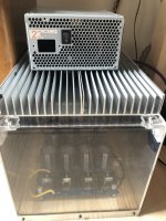
I feel that it is the increased current draw that causes it, as I increase the bias above 0.4V/0V offset.
Heatsinks also reach 55-60 degrees C, so I use a small fan on top to keep it lower. I am attaching my design’s photo too so you could picture.
Attachments

Just for reference as there are a few different variations of this schematic floating (pre/post turbo, pre/post P3), if you are using this schematic then yes, R7/R8 are the correct resistors to be measuring across to adjust bias
F5 schematic from diyAudio store

F5 schematic from diyAudio store
What design are you talking about? 'Surge protector' for voltage spikes or inrush current?Ah, but I already feed the power through an external thermistor/metal oxide varistor surge protector I had built.
Sorry, I obviously confused inrush current with voltage spikes. (Sorry about my inadequate knowledge. I am in fact a retired professor of molecular biology with strong interest in audio electronics). So you recommend Cl-60 in series with my tranny primary. Certainly. Just that Cl60 is not easy to come by here, would NTC 10D-15 suffice?What design are you talking about? 'Surge protector' for voltage spikes or inrush current?
look in datasheet of CL60, define size/Dia
find locally NTC having 10R, same or bigger Dia , and you're good
practically no other parameters being much important, under condition that you don't want less simple solution ( string of NTCs being shorted with relay after some time)
however, if good for original FW products, good enough for you
find locally NTC having 10R, same or bigger Dia , and you're good
practically no other parameters being much important, under condition that you don't want less simple solution ( string of NTCs being shorted with relay after some time)
however, if good for original FW products, good enough for you
I appreciate it, will do so.look in datasheet of CL60, define size/Dia
find locally NTC having 10R, same or bigger Dia , and you're good
practically no other parameters being much important, under condition that you don't want less simple solution ( string of NTCs being shorted with relay after some time)
however, if good for original FW products, good enough for you
From the datasheets I can find, the NTC 10D-15 is also a 10R, 5A part like the CL60. I would give it a try if you can find it locally.
And while at the store, please get some higher rated slow blow fuses that better match your transformer VA rating.
And while at the store, please get some higher rated slow blow fuses that better match your transformer VA rating.
Just ordered 10D-20 to match diameter. 🙏🏼🙏🏼🙏🏼From the datasheets I can find, the NTC 10D-15 is also a 10R, 5A part like the CL60. I would give it a try if you can find it locally.
And while at the store, please get some higher rated slow blow fuses that better match your transformer VA rating.
Dear all
With your most precious guidance I am finally a happy camper enjoying beautiful sound for the past couple days. I individually thanked some of you many times, yet, once again, I truly appreciate your patience with this novice.
Cheers.
With your most precious guidance I am finally a happy camper enjoying beautiful sound for the past couple days. I individually thanked some of you many times, yet, once again, I truly appreciate your patience with this novice.
Cheers.

I just wanted to follow up on my issues with F5 build and to come to a certain logical conclusion 🙂Dear Andy,
Thank you for your valuable opinion and for your suggestion!
It took me a bit longer to evaluate the second channel and to look back into the problem with the first one. However, I think that I found the problem.
With the second channel I was able to get 0.598 V and 0.602 V on MOSFET source resistors with 10mV bias offset. Which is, in principle, should be acceptable.
I then checked all the resistance values on the first channel, and find out that R2 is measured as appr. 15.8 kOhm on the board. I desoldered it, and it was all normal at 47.5 kOhm. I soldered it back in the board and checked resistance between several points on the board which having R2 involved - all gave non-correct values.
I started to suspect JFETs, I desoldered them and checked. I found that one of them is showing resistance between Gate and Source of 18.2 kOhm and 18.8kOhm depending on the polarity of probes.
I decided that it is a malfunction, which probably caused the uneven(unsymmetric) behavior of N and P parts of the circuit and lead to such a difference in currents. May be I handled it badly, or overheated while soldering...
I ordered new JFETs and will check the operation with them. They should arrive next week.
Maxim
But first of all, I wish to thank to all participants of this thread. Reading it, in general, and receiving answers to my own questions, in particular, was very educative and very helpful!
It took quite some time for me to come back to my F5 build after I received new JFETs, but now the amplifier is up and running for nearly 2 weeks.
However, I still wish to comment on my troubles with different currents in MOSFETs in one channel. Replacing a pair of JFETs did not bring any measurable difference. I still had about 15% of current difference in N and P MOSFETs. Thus, as a last resort, I decided to replace R7 and R8 to the new ones. And this was it.
After patient adjustments I obtained ~0.61V across R7 and R8 with <2% difference between them and <5 mV offset at the output (Very similar to what I got previously in another channel). After that I decided to stop and listen to music 🙂
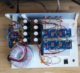
I am not sure yet about an enclosure, so my F5 is in transportable prototype mode. But it has no hum and sounds really great to me.
I use 400 VA transformer and my power supply with 8 x 10mF capacitors is based on Jeff Young boards design of Decoupled stereo PSU layout (I found Gerber files provided by Jeff on this forum). MOSFETs are mounted on heatsinks cooled by small fans.
My system at the moment is simple and straightforward. F5 is connected right to the output of my DAC (Pro-ject Audio DAC Box S2+, 2V output specified) using a 10-KOhm pot in between for volume control. My loudspeakers are DALI Oberon 5 with a nominal resistance of 6-Ohms and 88 dB sensitivity.
My first impressions after 2 weeks are that F5 sounds very clear, dynamic and engaging. Very nice bass control - deep and tight, I did not even know before that my Oberons are capable of this. The voices and acoustic instruments sounds very natural. And the stereo image is fantastic.
I am very happy that I decided to put myself into this project. So far, the best sound I`ve had at my home!
Attachments
- Home
- Amplifiers
- Pass Labs
- An illustrated guide to building an F5