I've just broken off one of the pins of my Schurter power entry module. Are you folks soldering hookup cable directly to these 3mm pins or using terminal clips? I'm having trouble finding terminal clips that would fit this, so I assume I'm missing something.

I've just broken off one of the pins of my Schurter power entry module. Are you folks soldering hookup cable directly to these 3mm pins or using terminal clips? I'm having trouble finding terminal clips that would fit this, so I assume I'm missing something.
I soldered 14g solid core straight to it.
same here. only it was 16awg for me. Haven't found the correct size for the quick connect tabs.
after clipping the last lead on these MOSFETs if occurred to me that maybe they should not be touching the PCB because they produce so much heat.
It's small but there is physical (nonconductive) contact here. Can anyone confirm if I need to try again with new devices to get them farther from the board?

It's small but there is physical (nonconductive) contact here. Can anyone confirm if I need to try again with new devices to get them farther from the board?
no
even if it is always better to avoid ugly looking bending of pins - when looking ugly, they're probably mechanically stressed
even if it is always better to avoid ugly looking bending of pins - when looking ugly, they're probably mechanically stressed
after clipping the last lead on these MOSFETs if occurred to me that maybe they should not be touching the PCB because they produce so much heat.
It's small but there is physical (nonconductive) contact here. Can anyone confirm if I need to try again with new devices to get them farther from the board?
That will be fine. The big resistors on the board are probably hotter than the mosfet case.
I'm understanding you to say that the edge overlap to the board is OK but my bend pins are bad form.
If that's the case then I can do better on my next board and thanks for the help
If that's the case then I can do better on my next board and thanks for the help
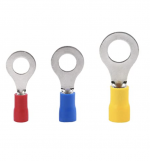
All of it is fine I think. Don't overthink it. You can save that power entry module by using the barrel of a crimp style eyelet of push on connector, cutting off just the barrel and using it as a splice between the wire and the tab. Crimp it down then solder it.
Attachments
Hey folks me again. Thanks again in advance.
Here's my amp, its all wired up and looking pretty. I brought up the power supply on a variac and it measured +25v and -25 and made me feel like the deft success I'd always hoped to be. All of my LED's are wired the right way too, which always feels good.

I'm having trouble getting the amp to bias. I'm measuring DC voltage across the 47r 3w resistors that are in the N and P channels. I carefully measured my trimpots and made sure that P1 + P2 were set to their minimum (0.5 ohms). A third voltmeter is across the speaker outs as per @ZenMod 's instructions in another thread.

I cannot get the voltage above the neighborhood of 50mV.
I had to remind myself that the V2 build guide is not 100% pertinent to the v3 board because parts numbers had changed. Once I figured that out, I was still befuddled.
So, here's where I am: no heat on the sinks, no burned or visibly damaged parts, hardly measuring above 50mV. What do I do?
Here's my amp, its all wired up and looking pretty. I brought up the power supply on a variac and it measured +25v and -25 and made me feel like the deft success I'd always hoped to be. All of my LED's are wired the right way too, which always feels good.
I'm having trouble getting the amp to bias. I'm measuring DC voltage across the 47r 3w resistors that are in the N and P channels. I carefully measured my trimpots and made sure that P1 + P2 were set to their minimum (0.5 ohms). A third voltmeter is across the speaker outs as per @ZenMod 's instructions in another thread.
I cannot get the voltage above the neighborhood of 50mV.
I had to remind myself that the V2 build guide is not 100% pertinent to the v3 board because parts numbers had changed. Once I figured that out, I was still befuddled.
So, here's where I am: no heat on the sinks, no burned or visibly damaged parts, hardly measuring above 50mV. What do I do?
Last edited:
How many turns on P1 and P2 have you tried from the minimum point? If I recall correctly, it took mine quite a few turns before the voltage started to creep up.
Hey folks me again. Thanks again in advance.
Here's my amp, its all wired up and looking pretty. I brought up the power supply on a variac and it measured +25v and -25 and made me feel like the deft success I'd always hoped to be. All of my LED's are wired the right way too, which always feels good.
I'm having trouble getting the amp to bias. I'm measuring DC voltage across the 47r 3w resistors that are in the N and P channels. I carefully measured my trimpots and made sure that P1 + P2 were set to their minimum (0.5 ohms). A third voltmeter is across the speaker outs as per @ZenMod 's instructions in another thread.
I cannot get the voltage above the neighborhood of 50mV.
I had to remind myself that the V2 build guide is not 100% pertinent to the v3 board because parts numbers had changed. Once I figured that out, I was still befuddled.
So, here's where I am: no heat on the sinks, no burned or visibly damaged parts, hardly measuring above 50mV. What do I do?
F5 Bias Problem
I've maxed the trimpots out in the right channel and still not near where I need them to be. I'm tired tonight but I'll repeat testing both sides of the amp again tomorrow when I'm fresh.
I've read through the above thread, looks like it's worthwhile to adjust the resistor that's in parallel with the trimpots to 3k3. I can try that this week too.
I've read through the above thread, looks like it's worthwhile to adjust the resistor that's in parallel with the trimpots to 3k3. I can try that this week too.
It's not necessary to install P3 unless tweaking the distortion.
P3 just unbalances the input stage source resistors.
P3 just unbalances the input stage source resistors.
Last edited:
If you do that, be sure to reset the pots to minimum before applying power.
Also, the amp will come up to bias much faster…so, go slow with your turns.
- Home
- Amplifiers
- Pass Labs
- An illustrated guide to building an F5