One week and going strong. I'm going to check the measurements later today.
I just got a REL sub and see attached for their recommended hook up to an amplifier.
I assume it will work fine with F5, but wanted to get some review on their approach.
I don't want to mess up my baby.
Thanks
Does the sub also have a low-level input?
One week and going strong. I'm going to check the measurements later today.
I just got a REL sub and see attached for their recommended hook up to an amplifier.
I assume it will work fine with F5, but wanted to get some review on their approach.
I don't want to mess up my baby.
Thanks
Go for it, if you have PSU common for both channels; if you have dual mono, result is shorting GNDs of two F5 channels, so no more dual mono
as McQ. said - cleaner and better if you can feed sub with line level signal, ditto from preamp outputs
though , same applies for preamp too - OK if PSU is common for both channels .........
Pictures
If I may quote you ZM," Pictures or it didn't happen"😀
Going to get more Beer and Tater Chips for the MX2 Movie!!!
Pictures of your F5 Chiptech
If I may quote you ZM," Pictures or it didn't happen"😀
Going to get more Beer and Tater Chips for the MX2 Movie!!!
Pictures of your F5 Chiptech
Last edited:
Go for it, if you have PSU common for both channels; if you have dual mono, result is shorting GNDs of two F5 channels, so no more dual mono
as McQ. said - cleaner and better if you can feed sub with line level signal, ditto from preamp outputs
though , same applies for preamp too - OK if PSU is common for both channels .........
My F5 is garden variety One PSU in the box.
Does the sub also have a low-level input?
Yes it does. Brand new unit from REL
while following chips adventures i recalibrated my own. they were set 5.5/0.xxx a channel.
I WOUND UP TO 6.25 COS I CAN AND IT WAS ABOUT TIME (liquid velvet). 3 wks...I read the damage report if mos fails (**** went). I twidle down to 6 .0 and whole upper mid and trebble have grown? is it because of 'burn in'? there is definately a high rise in the upper frequencies. thoughts please TY. temps bias and offset all good.
I WOUND UP TO 6.25 COS I CAN AND IT WAS ABOUT TIME (liquid velvet). 3 wks...I read the damage report if mos fails (**** went). I twidle down to 6 .0 and whole upper mid and trebble have grown? is it because of 'burn in'? there is definately a high rise in the upper frequencies. thoughts please TY. temps bias and offset all good.
Last edited:
the overall sound. the t and b defiately better at 625 mv. when reduced to 600mv treble and high mid have raised? i had a treb boost switched on at speakers. now i have it off and somehow....maybe a bit of paranoia but its just too sharp and fussy?. tannoy berkeleys. usually subdued in my experience. perhaps nothing ....
would seperating power ground from audio ground have anything to do with it in any waay as i did that while i was 'fiddlling'.?
Ah ok. while rearanging i missed out a direct audio ground to my new star audio ground. i assume that the full signal wasnt present as audio ground only connected to power ground via thermistor to work. i think... anyway working great now again.
I've had a half-finished F5 sitting on the bench for a few months. Watching Chiptech's issues has caused me to wonder if getting this running is actually above my pay grade but very glad to see it got sorted.
The PSU passed the dim bulb test a few weeks ago, so last night I finished the connections to the amp boards, set the trim pots to centre (12 turns clockwise from click), and powered up. Dim bulb passed again, Amp LEDs lit up and Velleman speaker protect relay clicked on as expected.
Now to bias. However I am not starting with 0 on all DMMs. These are V as I don't have mV,: R7, R8, Speaker:
Left 0.000 -0.01 -0.615
Right 0.000 -0.008 -0.525
The speaker offset is from the board output, not after the speaker protect.
Any thoughts on why I'm getting those readings on R8 and the output?
The numbers look fine to me.
You would expect the R8 value to be zero if P2 was turned all the way down,
so that you measure almost zero (or just a few ohms) resistance across R6.
In your case, you had adjusted the trim pots P1 and P2 to midpoint. So it looks
like Q4 is starting to turn on and you now see voltage across R8.
Your Q3 is not on yet, hence the zero voltage across R7 and the DC offset.
My suggestion is to start adjusting P1 to trim the DC offset down, say to
less than +/-50mV (or +/0.05V) Once you've done that then continue
with the biasing, alternating adjusting P1 and P2 to bring the voltage across R8
up, while keeping DC offset low.
Thanks Dennis.
P1 didn't seem to have any effect, but turning P2 clockwise has taken the DC offset down, I've set to around 50mV now.
However P1 still doesn't seem to be causing any changes. It seems to be the same on both channels as well.
Would I be better starting with both trim pots turned fully anticlockwise?
If you decide to begin fresh, don't worry about clockwise or anti-clockwise. Set both pots to where the resistance across R5 and R6 are as close to zero as possible.
Edited to add for clarity - P3, if installed, should remain in the middle.
Edited to add for clarity - P3, if installed, should remain in the middle.
Yes, as ItsAllInMyHead wrote, don't worry about clockwise or counterclockwise.
How much did you turn P1? Can you check that R5 and R6 are 2.21K? What
voltages do you measure across R3, R4, R5 and R6?
Can you try this: Power down the amp and measure the resistance across
R5 while adjusting P1 through its entire range. As P1 goes from 0 to 5K,
you should measure 0 to 1.5K across R5. Please verify that you have that. Then
adjust P1 again, until you measure close to zero at R5.
Then try the same with R6 and P1.
Thanks for the pointer on measuring the R range Dennis - I think I've got it; 200R and 5K trim pots in the wrong location - on both sides hence matching behaviour, I'll refit and report back 🙄
F-5 V1 or V2
Hello all, after finished an amazing Aleph J for my office, It's time to get for this Christmash a new toy, but, I need you well known.
If I understand well, with a good heatsinks, I can mount a F5 and put 32v per rail for then get 50w an move 4ohm speakers with enough dynamic, is called the F5 V1, very easy to mount really?
Till here Ok, but when you recommed mount then a F5 V2 for get 50 watts too ?? when you need more amp for a 3 way stand floor speaker or 85db 4ohm ??
I want to choose for one, but I have doubt, because I have the chasis, power supply and 700w 2 x 24v transformer.... but whats happen with the sound and performance, some times the most is not the better and simply is super.
Thanks for all.
It Always Comes Down To Nuts and Bolts
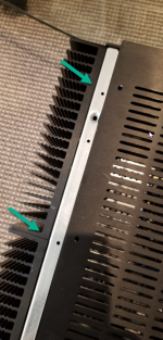
I've really been enjoying my new F5. Sounds great. I still get a thrill each time I turn it on and the blue lights glow.
I decided it was time to close up the case on the bottom and top. But I've discovered that the holes I thought I'd use are not threaded. So not sure how to proceed. It is the 5U case.
I'm working with a 4U case and the same holes are threaded, so not I'm confused. Did i just get unlucky and my rails were not done correctly?
See photo.
Thanks
Attachments
- Home
- Amplifiers
- Pass Labs
- An illustrated guide to building an F5