Thanks. I appreciate all the coaching. My plan is to start biasing tomorrow afternoon.
So as I progress my target is to get the bias resistors to around 250 mV and then let the amp cook for 30 minutes to 1 hour.
After a few days I should be able to bias the amp higher to values of 300 mV to 400 MV.
Correct?
So as I progress my target is to get the bias resistors to around 250 mV and then let the amp cook for 30 minutes to 1 hour.
After a few days I should be able to bias the amp higher to values of 300 mV to 400 MV.
Correct?
You are building a standard F5 (not an F5 turbo). The bias current is about 1.3A
so your final target is about 0.6V (or 600mV) across the 0.47 ohm source resistors.
The main thing is to adjust (increase) the bias by alternatingly adjust P1 and P2
while keeping the DC offset low (say within +/-50mV)
Adjust the bias one channel at a time.
For the first round, perhaps try targeting for about 400mV across the source resistors
and low DC offset. Let the channel cook for an hour (with lid on) and then trim
the DC offset if needed. The bias will probably have drifted a bit but don't worry about
that since you're still somewhat away from your final target.
Now repeat for the second channel.
Bias Notes
One item to remember is while you are adjusting the bias, DON'T breathe, don't fart, no fan or moving air. The jfets are very sensitive to temperature change.
Remember P1 and P2 are interrelated change either one and all three DVM's will change. Just make small changes 1/2 turns until you get it figured out. The ouput offset is the important one. Try to get this dvm as close to 0.0 as you can. There will be drift. As Dennis said get each channel to about 400mv. One at a time.
When I biased my F5, I stopped at 450mv on both channels. Just a number I picked. I then hooked up both channels for a test. I listened to music for 3 or 4 days at this setting. Sort of like a test run.
Gonna go outside to work on my Fence, when I get back, I expect to hear good news and some MUSIC.
You got This Chip😀
Ty
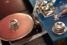
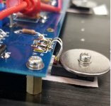
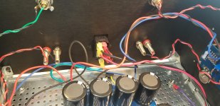
Chiptech - Please move the thermistors so they contact the plastic case of the MOSFET, not the metal fender washers. They are known to short out when contacting metal to ground.
Ok I have moved the thermistors. Thanks
Attachments
You'll need to turn the pots about 5 times around each until you see voltage, then slow down to 1 turn, then less as it comes up. Go back and forth keeping the voltages roughly the same. Watch what each pot does to the DC offset voltage. Check mosfet and heatsink temps (they should be close). Feel free to bias up to .6v right away and go to .7 if you are a fearless builder. Let it cook for an hour or two, check temp which should be around 120F, adjust voltages, then put the top on and enjoy the music.
To be clear, get them to .6v = mV
That's where I'm at and not getting any heat yet.
the out put is at 0.6 mV.
15 minutes later:
R7 = 1.2 mV
R8 = -1.0
Output = 0.0 mV
Per A321Divr: "Remember P1 and P2 are interrelated change either one and all three DVM's will change. Just make small changes 1/2 turns until you get it figured out. The ouput offset is the important one. Try to get this dvm as close to 0.0 as you can. There will be drift. As Dennis said get each channel to about 400mv. One at a time."
I see I have a ways to go. So I will proceed slowly.
Attachments
Last edited:
Thanks.
And output not to exceed 50mV
I'm at 450 mV and 0.0 mV at output.
Heat sinks getting warm.
Going to let it sit for a while.
And output not to exceed 50mV
I'm at 450 mV and 0.0 mV at output.
Heat sinks getting warm.
Going to let it sit for a while.
Last edited:
Progress Report
I came inside to take a break, have to let some concrete setup. I got so excited I had to get a Beer.
Looking good on you bias process.
Won't be long now
I came inside to take a break, have to let some concrete setup. I got so excited I had to get a Beer.
Looking good on you bias process.
Won't be long now
Ok to push to 600 mV today if all looks good after an hour?
I've read sometimes people wait.
heat sinks are warm to the touch, not hot
I've read sometimes people wait.
heat sinks are warm to the touch, not hot
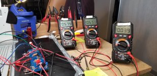
I'm at:
R7 = around 582.5
R8 = around -591.5
Output =- 0.8
It has been cooking for around an hour.
I think I will declare victory for the right channel and do the left channel tomorrow.
Thanks again for all the counsel and support.
Almost there.
R7 = around 582.5
R8 = around -591.5
Output =- 0.8
It has been cooking for around an hour.
I think I will declare victory for the right channel and do the left channel tomorrow.
Thanks again for all the counsel and support.
Almost there.
Last edited:
OK. Assuming you are building stereo with a single power supply, be prepared
to trim the bias again with both channels attached.
Also, don't worry if the voltages across R7 and R8 aren't identical. The important
thing is they are close to your target and the dc offset is close to zero.
to trim the bias again with both channels attached.
Also, don't worry if the voltages across R7 and R8 aren't identical. The important
thing is they are close to your target and the dc offset is close to zero.
Getting there 🙂I'm at:
R7 = around 582.5
R8 = around -591.5
Output =- 0.8
It has been cooking for around an hour.
I think I will declare victory for the right channel and do the left channel tomorrow.
Thanks again for all the counsel and support.
Almost there.
I assume your measurement units are mV?
Chiptech,
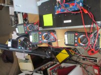
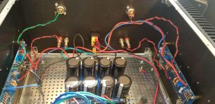
Looking at the photo in post #1686 I want to point out a couple things.
1) Your channel is not in a completed chassis so it's in a different
thermal environment than its final configuration. Since the bias
is affected by temperature, you will need to readjust the bias when
you have the channel in a chassis. I need to reiterate that the final bias
adjustment can only be done with both channels completed in the chassis.
And you need to 'cook' the channels with the lid on, and only take it off
briefly for adjustments.
So right now, you shouldn't try getting those voltages to your final
target since you'll need to readjust when you have everything put
together.
2) You have the multimeters measuring R7 and R8 set to mV scale.
As far as I'm able to find out, your HT118A meters can measure up to
600mV on the mV scale. Above that it probably will show 0L or
something similar. If you're already close to that limit, you can
switch to "V" scale instead and just target for 0.6V. This way, you
won't be confused if you suddenly see the meter give 0L if those
voltages drift above 600mV.
Also, when you post numbers, please always indicate measurement
units to avoid any misunderstanding.
Getting there 🙂
I assume your measurement units are mV?
Yes they are.
Chiptech,
Looking at the photo in post #1686 I want to point out a couple things.
1) Your channel is not in a completed chassis so it's in a different
thermal environment than its final configuration. Since the bias
is affected by temperature, you will need to readjust the bias when
you have the channel in a chassis. I need to reiterate that the final bias
adjustment can only be done with both channels completed in the chassis.
And you need to 'cook' the channels with the lid on, and only take it off
briefly for adjustments.
So right now, you shouldn't try getting those voltages to your final
target since you'll need to readjust when you have everything put
together.
2) You have the multimeters measuring R7 and R8 set to mV scale.
As far as I'm able to find out, your HT118A meters can measure up to
600mV on the mV scale. Above that it probably will show 0L or
something similar. If you're already close to that limit, you can
switch to "V" scale instead and just target for 0.6V. This way, you
won't be confused if you suddenly see the meter give 0L if those
voltages drift above 600mV.
Also, when you post numbers, please always indicate measurement
units to avoid any misunderstanding.
Dennis, Thanks for the above. I will follow it exactly once I have the left channel done as the right and build the box back together.
Very helpful. Especially mV to V.
Tuesday Morning
I assembled everything together and ran a dim bulb test.
Failure.
So I then tested the PSU. That works.
Then the right channel by itself. Failure.
Left channel by itself. Failure.
I've checked all my connections.
I checked the mosfets for a ground issue. Nothing.
All the LEDs light up.
Appreciate any ideas.
Attachments

- Home
- Amplifiers
- Pass Labs
- An illustrated guide to building an F5