Moving from 5mm standoffs and Keratherm to Aavid. I considered the Keratherm thickness when compressed to be 'negligible' and the rigid Aavid insulators at 2mm thickness. So, I thought a 7mm standoff may work well. I don't necessarily tighten my boards "too tight" and just use the standoffs for general stability.
That should keep stresses off the pins, I think, and still allow for a nice board mount. I ordered some 7mm for use with the boards I previously soldered with Keratherm pads to use with the Aavid insulators. However, I haven't tried it yet. If I see any potential downward board bend, I can insert a thin nylon washer between the standoff and the boards. I don't think they'll be too long. I'll still potentially give the output devices a quick wipe along all three pins at once with a wide iron tip to re-flow if necessary.
That should keep stresses off the pins, I think, and still allow for a nice board mount. I ordered some 7mm for use with the boards I previously soldered with Keratherm pads to use with the Aavid insulators. However, I haven't tried it yet. If I see any potential downward board bend, I can insert a thin nylon washer between the standoff and the boards. I don't think they'll be too long. I'll still potentially give the output devices a quick wipe along all three pins at once with a wide iron tip to re-flow if necessary.
@ chip. I bought a set of F5 boards with the intent of one day building them. If there is a store delay, happy to send you a set to get started and you can replace them when yours finally come in. PM me if interested.. dB
Thanks very much. I have procured the.
Now I just have to be a little patient.
Start dreamin' of my next NP amp build.
But only after this one id done.
Now I just have to be a little patient.
Start dreamin' of my next NP amp build.
But only after this one id done.
Hello..
I started reading this thread but it is now 167 pages long so might take quite a while for novice like me. I recently got F5 clone and torroidal transformers inside hum a bit and can hear the low hum when I very close to the amplifier.
Hence, I am thinking to add DC blocker to help reducing torroidal hum.
Would this be okay adding DC blocker into F5 amp?
This is the PCB for DC blocker that i have in mind.
https://www.atlhifi.com/shop/bare-p...ker-filter-for-toroidal-transformers-toroids/
Thank you very much..
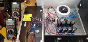
Here is a quick snapshot to see inside. 2 x large 300VA torroidal transformers inside.

If DC blocker is not a good idea, i am thinking to add Sorbothane sheets under the torridal transformers to reduce hum a bit.
Thank you..
If DC blocker is not a good idea, i am thinking to add Sorbothane sheets under the torridal transformers to reduce hum a bit.
Thank you..
Moving from 5mm standoffs and Keratherm to Aavid. I considered the Keratherm thickness when compressed to be 'negligible' and the rigid Aavid insulators at 2mm thickness. So, I thought a 7mm standoff may work well. I don't necessarily tighten my boards "too tight" and just use the standoffs for general stability.
That should keep stresses off the pins, I think, and still allow for a nice board mount. I ordered some 7mm for use with the boards I previously soldered with Keratherm pads to use with the Aavid insulators. However, I haven't tried it yet. If I see any potential downward board bend, I can insert a thin nylon washer between the standoff and the boards. I don't think they'll be too long. I'll still potentially give the output devices a quick wipe along all three pins at once with a wide iron tip to re-flow if necessary.
I'm using 5mm stand offs. Or should I move to 10mm?
I would use 10mm given a choice. 5mm doesn’t leave much room for solder blobs and connection wires under the boards. And the heatsink is pretty hot. Better give it some room.
I'm back.
All new boards and parts.
Everything double checked.
Gave the PSU a dim bulb test and it passed.
I lowered both trimpots to .2 do i need to go lower before powering up?
The right channel passed the dim bulb test.
Thanks all
All new boards and parts.
Everything double checked.
Gave the PSU a dim bulb test and it passed.
I lowered both trimpots to .2 do i need to go lower before powering up?
The right channel passed the dim bulb test.
Thanks all
Attachments


I would use 10mm given a choice. 5mm doesn’t leave much room for solder blobs and connection wires under the boards. And the heatsink is pretty hot. Better give it some room.
Thanks, will do.
Wire Color
Hey Chiptech,
Make sure you have the wiring correct from the power supply as well as the inputs and speaker terminals. Using the same wire color for multiple things can get you into another mess.
How about some pictures of the back of the amp and power supply so everyone can help you double check the wiring.
Fingers Crossed, Beer in Hand, Standing By.
I’m ready to bias my right channel.
My PSU passed the dim bulb test.
The right channel passed the dim bulb test.
I adjusted P1 and P2 without unit plugged in to 0.0 to -0.1 range.
I’ve read several different direction sets on how to do this and I’m using cubincher’s guide from Another F5 Build post 106 and 109 as it seems the most detailed step by step to guide me. Thanks to A321Dryr for pointing me to it.
I’ve set up my 3 DMMs:
1. Loudspeaker output – set to mV
2. R8 mV
3. R7 mV
I turned the amp on and all three DMMs show 0.0 mV.
I’m ready to:
Turn P1 slowly [very] till the DMM shows 0.1 to 1mV
Same for P2.
The output DMM should not exceed 50 mV.
Then adjust P2 till offset at output is close to 0 mV.
Wait till offsets stabilize.
Here is where I’m unclear:
Turn P1 a little bit higher till offset at output is at 50 mV, then turn P2 a little bit higher till offset at output is close to 0 mV again.
If I’m turning both pots up, how can I lower the offset back to 0 mV? I think that is the magic of + and -polarity?
Thanks for all the help getting me here and guiding me thru a successful biasing.
The idea is that the difference in current through the two sides show up
as the dc offset.
So you can turn up both sides, and as along as their currents are close,
the dc offset should be low.
as the dc offset.
So you can turn up both sides, and as along as their currents are close,
the dc offset should be low.
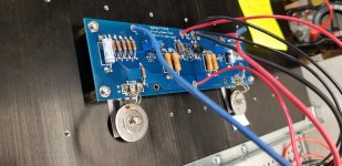
Chiptech - Please move the thermistors so they contact the plastic case of the MOSFET, not the metal fender washers. They are known to short out when contacting metal to ground.
- Home
- Amplifiers
- Pass Labs
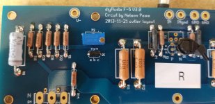
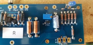
- An illustrated guide to building an F5