Using +/- 33V I would advise building the F5 Turbo v3 (which has the cascode front-end) and use as many output devices as you have heatsink capability. You can use any number of output mosfet, even one pair, the point of looking at the v3 is the cascode to use higher voltages without risking the input Jfet.
http://www.firstwatt.com/pdf/art_f5_turbo.pdf
Thank you AndrewT and 6L6,
I'm building at the moment a C12, I have a U4 case and a 24V Tx, once done I just changing pcb I can easily go to F5T.
Thank you so much for the reply. So I may try it out while waiting for the LIS to finally catch up with demands here.
Hi, could any of you learned fellows please advise me. Do i need to re-adjust bias/offset if i add more capacitance? Or should i be ok? i have bias at .570 and offset at 0.00 both channels but i only have 40,000uf total and want to upgrade to 60,000uf per channel.
thank you in advance
Regards Brian
thank you in advance
Regards Brian
If you don't have any PSU hummm you don't need to change anything. Bias and PSU capacitance are not really interlinked.
If you don't have any PSU hummm you don't need to change anything. Bias and PSU capacitance are not really interlinked.
Thank You 6L6 and also for the many illustrated guides.(of course i followed your F5 build). Excellent work.
I can hear a very slight hum if i put my ear to my speaker cone. It does not get louder with volume +.
I have 2 channels in 3u chassis 625va 16.5A dual 18v.
I took it as granted i would have some hum.
what do you think. I dont want to break it (just yet😱). Should i saw chassis in half and make mono or basically is my wiring rubbish
 .
.i will of course look into it.
thank you.
I think I answered my own question... perhaps best to try to get rid of hum first.
Last edited:
Okay Thank You 6L6. I sort of ignored the psu layout with the r4.7s as i only had a stereo type psu pcb setup and forgot. Im on track. Cheers.
Hi DIYers. I have a problem, maybe someone can help me. I built my first F5 and did the bias settings, then i realized that i made a mistake by interchangin the BEC legs on both the ZTX450 and 550... so i de-soldered them and soldered back correctly... After firing it up, both power resistors (0.47ohm 3W) when into smoke...
My theory is that the ZTX's when away during the first start when they were connected wrong. Any ideas?
My theory is that the ZTX's when away during the first start when they were connected wrong. Any ideas?
desolder them and replace
also - desolder JFets and check them in matching jig (9V battery as voltage source will do)
check mosfets at least for shorts between pins
re-read setting procedure in post #2
also - desolder JFets and check them in matching jig (9V battery as voltage source will do)
check mosfets at least for shorts between pins
re-read setting procedure in post #2
Even though I'm a little embarrassed by, it I'd like to share something that happened during my F5 build. It may help someone later on. I had just finished mounting the mosfets to the heat sink and before powering it up I decided to check continuity between the mosfet and heat sink. To my surprise I got a loud continuity beep. So I took everything apart, resoldered etc, but still had continuity. I finally discovered that it was via one of the pcb mounting screws. I had used a washer from the top and that washer had been tightened and twisted enough to scratch through the solder mask layer thus connecting one the traces to the sink. I learned that I should be careful to use the smooth side of the washer against the board. I put some non-glitter nail polish over the scratch and everything turned out fine--sounds great. Dumb mistake but it took me a long time to find it. Live and learn...
if you have washer against pcb track , put either hard plastic or hard cardboard washer first , then metal washer
leaving just stop lack for insulating against metal is big no-no
leaving just stop lack for insulating against metal is big no-no
Yep. I learned that the semi-hard way. Luckily I did the continuity check before powering up. Now I've got a large stock of little plastic washers 🙂
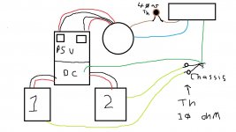
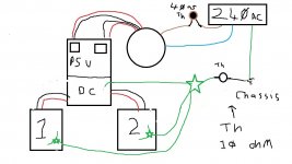
Hi, first and foremost, thanks for the excellent guide!
I'm just wondering, would this work for me? I live in the UK and we have 240v ac power at 50hz... If it does then great! will be building this beast soon, if not what would you have to do in order to be able to use this amp with the UK power supply? could i just buy a step down transformer? any help would be greatly appreciated thanks 🙂
I'm just wondering, would this work for me? I live in the UK and we have 240v ac power at 50hz... If it does then great! will be building this beast soon, if not what would you have to do in order to be able to use this amp with the UK power supply? could i just buy a step down transformer? any help would be greatly appreciated thanks 🙂
You build the amp with a UK spec transformer, that's all.
Hi colin thanks for the reply, could you recommend any? thanks
I used this one from RS to minimise shipping. Mine is totally silent.
RKD 400/2x18 | 2 Output Toroidal Transformer, 400VA, 2 x 18V ac | Block
Try to get J-fets from someone like Spencer on here or from the shop. Do not trust E-bay unknown sellers.
RKD 400/2x18 | 2 Output Toroidal Transformer, 400VA, 2 x 18V ac | Block
Try to get J-fets from someone like Spencer on here or from the shop. Do not trust E-bay unknown sellers.
These guys make good transformers. Get one with an interwinding screen and a Goss band.
https://airlinktransformers.com/pro...toroidal-transformer-standard-range-cm0500218
https://airlinktransformers.com/pro...toroidal-transformer-standard-range-cm0500218
Hi, i am thinking of building an F5 to power near or midfield studio monitors. I suspect that 25w may be a little under what I need as they tend to be a little less sensitive than my big open baffles that my single F4 powers quite happily.
The obvious response is "why dont you build the F5 turbo?"
Well, I was thinking that the F5t does 50w per side and is quite happy in a 5U chassis, but then i think i also have to mess around matching my output transistors.
I was thinking about putting 2 normal F5s in a 5u chassis so i can biamp. probably dual psu rather than one big one.
Any thoughts on this?
- Home
- Amplifiers
- Pass Labs
- An illustrated guide to building an F5