Thanks all for answers on torque question.
you can always count on us , when something needs screwing up

😕 Oh dear it was all going so well.
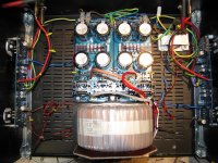
I got both sides running and biased to .6v all temps fine everything stable.
Let it soak test for several hours with the lid on all fine.
I connected interconnects to the pre-amp which had been measured and tested into my existing valve amp.
Switched on and the magic smoke escaped from one channel!
Bias voltage went high.
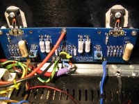
The 0.47 bias resistors got hot and on a quick look the mosfets at least look fried.
Back to the bench and the other channel tests fine and is still stable.
Any clues to look at when I have the board repaired?
😕 Oh dear it was all going so well.
I got both sides running and biased to .6v all temps fine everything stable.
Let it soak test for several hours with the lid on all fine.
I connected interconnects to the pre-amp which had been measured and tested into my existing valve amp.
Switched on and the magic smoke escaped from one channel!
Bias voltage went high.
The 0.47 bias resistors got hot and on a quick look the mosfets at least look fried.
Back to the bench and the other channel tests fine and is still stable.
Any clues to look at when I have the board repaired?
This looks similar to my problem. Did you get also the gate resistors (R13,...) smoked up? Please update once you check the mosfets. Will you go as back as the ZTXs?
Have not checked any further yet.
R7 R8 got hot but they are 5w wire wound and seem to have survived.
More checks tomorrow now when I tale the board off.
R7 R8 got hot but they are 5w wire wound and seem to have survived.
More checks tomorrow now when I tale the board off.
Offset was checked at a couple of mv, no problems when connected to existing valve amp for test.
Pre is JC-2 from jims audio (pre built and tested)
Pre is JC-2 from jims audio (pre built and tested)
More on mounting torque
The maximum torque is determined by the device's package. You can look it up in the datasheet, as in the one linked below:
http://www.vishay.com/docs/91210/91210.pdf
In the grid labeled ABSOLUTE MAXIMUM RATINGS, look at mounting torque. I use a torque driver adjusted for 8 lbf-inch.
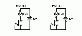
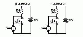
A while back I was asked, through private messages, about mounting torque and decided to conduct some experiments. For those who do not have a torque driver and torque analyzer, I suggest the following:
1) Mount the MOSFET and all associated hardware on the heat sink without tightening the screw
2) Looking from the side, tighten the screw until no gap is visible between the involved parts: screw, washer, MOSFET, insulator, heat sink
3) After making all parts snug, looking from the top, turn the screw an additional 1/5 of a turn
OK still a problem here.
Replaced all the semiconducters on the board with new.
No resistors looked burnt so did not lift them to check.
Powered up (with bulb) and adjusted bias as usual.
Only seeing voltage rise across one 0.47 resistor (N side mosfet)
and all 4 100r 3w resistors are getting hot.
Suggestions welcome, but looks like a complete strip next time.
Indeed... Don't tear it all apart and blindly replace bits without knowing what is causing the malfunction.
Please post some well-lit, in-focus photos. There are people on this forum that can see the most amazing things through the screen
Please post some well-lit, in-focus photos. There are people on this forum that can see the most amazing things through the screen
Hi again
Thanks for being patient with me.
Some more testing this morning and all resistors seem ok.
Power on with bulb tester (5K pots measured and checked at zero.)
Across R15 324mv (P)
Across R16 0.0mv (N)
Offset 20v (yes 20v!)
R9,10,11,12 getting hot.
All semiconductors replaced with new yesterday.
This board was working well until I connected it to pre-amp. (not connected now.
Mosfets were from digikey.


Any clues where to check?
Or shall I take it apart and start again?
Any simple check for the semiconductors?
Or shall I take it apart and start again?
Any simple check for the semiconductors?
Thanks for the comments.
I have music 🙂
I will let it settle and listen for a while.
Could you let me know what was the problem, the solution and what checks you carried out? Mine seems similar to yours (i.e. high current which blew out R7, R8 and R13 - post #864).
First problem after connecting pre-amp was blown Mosfets and jfets.
All semi-conductors replaced.
Rebuilt and got voltages posted above. (with bulb tester connected)
I lifted all the resistors and checked them, all were ok.
Semi-conductors lifted again, checked and replaced carefully checking against circuit.
P1 & P2 replaced, then zeroed across R5 & 6, not just separately.
Back on bulb tester, then without, and voltages came up fine, soak tested at full power for several hours and all fine.
Not wanting to risk the preamp again I substituted a quick and dirty passive 10K pot.
Sounds very good to me now.
In short multiple checking that semis are in the correct orientation with P & N correct and pin outs correct.
Hello All,
I'm not really familiar with the F5 but have built a lot of amplifiers for the hobby (including tube amps) and I thought of trying the F5.
Normally before I built a new amplifier I always check for components and " built" de schematic in a simulation (TINA from DesignSoft) and play around
with a lot of changes and settings and until now the results of these simulations are almost always correct or near correct with reality.
BUT I have tried to make this F5 working in the simulation and whatever I try this F5 is always very unstable and will not work 😡
What I see a lot is that the output jumps from +24V to -24V (powerrail) so
almost all the time one havle of the amplifier "collapses" and this is what al also read in some treads.
Just to be sure I have checked all the used spicemodels of the fets in a different design that I already built and there they work perfectly in the simulation.
So in my humble opinion 😱 this design can not work propperly.
This puzzles me because a lot of people built this amp and claims that it works fine but I also read a treads of people who encountered a lot of problems.
Is this F5 amplifier a unstable design or am I missing something 😕
This puzzles me because a lot of people built this amp and claims that it works fine but I also read a treads of people who encountered a lot of problems.
Is this F5 amplifier a unstable design or am I missing something 😕
F5 models stably for me and, if anything, my actual F5 is even more stable.
- Home
- Amplifiers
- Pass Labs
- An illustrated guide to building an F5
 [AGAIN!]


