**** up, you’re gonna trigger my OCD and numerology skitzophrenia 😝😝🤓Technically, if you are using 0.75in wood, then it should be 1.905cm or 1.91cm in HR.
if you notice , my folds are all exactly pi x10 inches long, lol! And I canceled out 432 hz

TL bit in the Great Sound thing
Everything written on TLs before King/Augspurger requires re-examination and likely expounds seat-of-the-pants — and shown not at all optimum — “classic” design methodology.
dave
The function you used in HR plus your measurement proves that Paraflexes are BP8P enclosures.
Each peak in the Electrical Impedance = 2 orders.
4 peaks × 2 orders = 8th order.
You can't get any simpler than that math.
Sealed enclosure = 1 peak or 2nd order.
Each peak in the Electrical Impedance = 2 orders.
4 peaks × 2 orders = 8th order.
You can't get any simpler than that math.
Sealed enclosure = 1 peak or 2nd order.
🤣😂🤣😂**** up, you’re gonna trigger my OCD and numerology skitzophrenia 😝😝🤓
if you notice , my folds are all exactly pi x10 inches long, lol! And I canceled out 432 hz
Not sure, do you have a pic by chance?
Not me, But bp1 just did: Not a great one.
Both the front and back of the driver are in the lime, a single tapped horn is also called a Voigt.
dave
My only ‘argument’ is that all pipes have multiple resonances, so what you’re seeing as another electrical inpedance isnt the result of another chamber/vent, it’s in all ‘TL’ regardless, but even ‘more‘ obvious as you bring the vent exit closer to the driver by folding it Into the common subwoofer designs??The function you used in HR plus your measurement proves that Paraflexes are BP8P enclosures.
Each peak in the Electrical Impedance = 2 orders.
4 peaks × 2 orders = 8th order.
You can't get any simpler than that math.
Sealed enclosure = 1 peak or 2nd order.
TL enclosures do not have buried drivers or the driver is mounted on top of the enclosure.My only ‘argument’ is that all pipes have multiple resonances, so what you’re seeing as another electrical impedance isn't the result of another chamber/vent, it’s in all ‘TL’ regardless, but even ‘more‘ obvious as you bring the vent exit closer to the driver by folding it Into the common subwoofer designs??
The 2nd or 3rd chamber makes a difference in measurements.
Like BR's, TL's are single chambered enclosures.
regarding the tapped horn shapes and issues, verses the plain pipe shape:
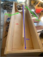
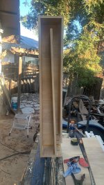
i find it incredibly interesting/weird that both of these 320liter folded pipes with completely different lengths(3 meter vs 6 meter) and shapes (straight TL with driverat high pressure end vs Paul Voigt type conical flare pipe with driver located at the mid point/velocitymax for 57.6 hz) result in the same frequency response, but the other has the even numbered resonances mixed in with the odd?
Last edited:
I keep making these because they seem to sound the best, but it’s a ‘6th order‘ according to the impedance measurement (but only because it’s long enough to have all those resonances) so I ignore the naming conventions and fake arguements?TL enclosures do not have buried drivers or the driver is mounted on top of the enclosure.
The 2nd or 3rd chamber makes a difference in measurements.
Like BR's, TL's are single chambered enclosures.
Attachments
Voigt Pipe = TL.
JBL Air Coupler = TH.
Vigt = single tapped
JBL = double tapped
dave
the stepped horn shaped resonator parts arent even long enough to individually contribute to the bandwidth so.....(i dont see this as an added 'order' as a result of another 'chamber') and..... see how ambiguous and confusing this stuff is? it typically doesnt even make much sense to try and over analyze it unless you can remove one of those sections and observe its contribution in horn response to actually be related to the babdwidth ?
Both models are a type of TL enclosure.regarding the tapped horn shapes and issues, verses the plain pipe shape:
i find it incredibly interesting/weird that both of these 320liter folded pipes with completely different lengths(3 meter vs 6 meter) and shapes (straight TL with drive rat high pressure end vs Paul Voigt type conical flare pipe with driver located at the mid point/velocity max for 57.6hz) result in the same frequency response, but the other has the even numbered resonances mixed in with the odd?
You cannot model a TH with the Nd or OD functions in HR.
TH = BP6S.
You can model BP6P's with the Nd, OD, CH, or BP6P functions in HR.
You can model TH's with the TH and BP6S (straight flare only) in HR.
Scoops can be model as a BR with a positive flare port or as a compression chambered (Vtc/Atc + Ap1/Lp) TH, if the driver is mounted offset in the horn's path.
The enclosure on the left in pic 1 is a compression chambered TH Scoop.
The enclosure on the right in pic 2 is a Nd or OD Scoop.
The 2nd pic is from Tom Danley's patent...compression chambered TH.
Voigt = single tapped
JBL = double tapped
dave
Do you consider a sealed or BR enclosure tapped?
If not, then a TL is not tapped.
No center port is BW's folded T type BP6P.
The rear chamber is the port.
View attachment 1357858View attachment 1357860
ok,
so like this ?
so simulate the difference in the ever so slightly gigantic flared version with driver motor ’barely’ in the vent verses the other and there’s nothing to see/hear?Both models are a type of TL enclosure.
You cannot model a TH with the Nd or OD functions in HR.
TH = BP6S.
You can model BP6P's with the Nd, OD, CH, or BP6P functions in HR.
You can model TH's with the TH and BP6S (straight flare only) in HR.
Scoops can be model as a BR with a positive flare port or as a compression chambered (Vtc/Atc + Ap1/Lp) TH, if the driver is mounted offset in the horn's path.
View attachment 1357985View attachment 1357986
The enclosure on the left in pic 1 is a compression chambered TH Scoop.
The enclosure on the right in pic 2 is a Nd or OD Scoop.
The 2nd pic is from Tom Danley's patent...compression chambered TH.
View attachment 1357992View attachment 1357993
Wherever a driver enters the ‘box’ is the ‘tap’ . I believe this is even the terminology used for eiectrical circuits and heating/air conditioning ducts and intake/exhaust systems with stubs and offset resonaturs as well as the end of the closed or open exhaust valve?Do you consider a sealed or BR enclosure tapped?
If not, then a TL is not tapped.
the stepped horn shaped resonator parts aren't even long enough to individually contribute to the bandwidth so.....(i don't see this as an added 'order' as a result of another 'chamber') and..... see how ambiguous and confusing this stuff is? it typically doesn't even make much sense to try and over analyze it unless you can remove one of those sections and observe its contribution in horn response to actually be related to the bandwidth ?
I could not find a Paraflex C-2E electrical impedance measurement.
Here is a Paraflex C-2A electrical impedance measurement.
There is a 4th peak around 160-170hz (orange line), it is slight though.
The model did not match the build. I wonder if they used the TH function vs the PH function in HR.
Anyways, the C-2A has a similar design to the C-2E.
They are both BP8P enclosures.
I can SEE the C-2A's rear chamber and 2nd port are combined (same CSA) and the area right behind the enclosure's mouth is the 3rd chamber.
https://forum.speakerplans.com/topic106775.html
- Home
- Loudspeakers
- Subwoofers
- An idea: A T-line with both ends open