Here is a short description of the circuit:
Front-end
The first stage is a FET, to allow the connection of any type of probe, including the electrostatic, high impedance one with a minimal noise penalty.
The second stage is a plain-vanilla, common-emitter amplifier having a switchable gain.
The total gain is ~20dB/40dB.
The input is protected against moderate abuse by R1 and D1, D2.
As the PSRR of the preamp is not very high, the supply is made extra-clean thanks to the combined gyrator/cap-multiplier built around Q2, and the bypass cap C3.
Filters
After the first section of the gain potentiometer, the signal is sent to two cascaded bandpass filters U1B and U2B.
In addition to the 3 frequencies, the selector also allows a ~flat amplification with R13 and R20 as feedback resistors.
U1A generates a virtual GND from the clean preamp supply.
Some of the gain available is thrown away with R14 in series with the second section of the gain potentiometer: with the simplistic BPF topology used, the gain and Q are correlated, and to arrive at a high Q and a good selectivity, it is necessary to have a gain in excess of 2,000 for each stage.
That is more than 4,000,000 for the two stages, ~135dB.
Added to the 40dB of the front-end, It would result in a total of 175dB, which is vastly excessive.
U2B is a LM324, and because it is used well beyond its gain and bandwidth capabilities, it becomes unstable and tends to oscillate at the filter frequency, probably because of the awkward output characteristic of the 324.
R16 biases the output in class A, eliminating the instability.
Post-processing
The filtered signal is rectified by U2C and the associated components. The circuit looks convoluted, but it is quasi-fullwave, with a semi-log characteristic for very low levels, which is helpful in this tester.
The resulting level is further amplified by U2D and sent to the V-F converter U2A.
The VFC output consists of narrow pulses, to make a maximum of noise with a minimal current consumption.
The signal can also be sent directly to the audio amplifier, but this is useful mainly in flat mode: the filtered, low-frequency sinewaves aren't very audible, even with headphones, and they are completely inaudible on the small built-in speaker.
The audio amplifier U3 is a completely ordinary LM386.
The DC output is sent on a small galvanometer, using a FET circuit instead of a simple resistor, to magnify the low levels.
The DC voltage can also be connected to an external meter, to be able to make accurate comparisons between two situations for example.
It is also possible to increase the averaging time, to eliminate temporary fluctuations.
All of that is icing on the cake, and doesn't need to be implemented if you do not feel the necessity.
The total current consumption is comprised between 12 and 16mA
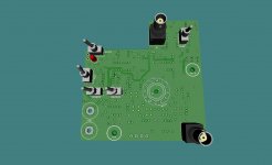
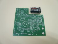
Rotary and toggle through hole switches checked. Only thing I can't find locally is the upright BNC so it has to be ordered. Final adjustments to the pcb and it's ready for order too. First time I'm doing this since the latest EU import policy changes. Let's hope for the best... My 3D library is incomplete but I think you get the picture.
Meanwhile, I'm building the probes. Instead of 10mH, I found 8,2mH otherwise the same type as suggested. Could I use it? Also, the copper shield around it should cover only its circumference or top and bottom as well?
Only thing I can't find locally is the upright BNC so it has to be ordered. Final adjustments to the pcb and it's ready for order too. First time I'm doing this since the latest EU import policy changes. Let's hope for the best... My 3D library is incomplete but I think you get the picture. Meanwhile, I'm building the probes. Instead of 10mH, I found 8,2mH otherwise the same type as suggested. Could I use it? Also, the copper shield around it should cover only its circumference or top and bottom as well?
Attachments

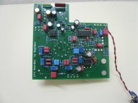
I didn't check in every detail, but the picture looks OK.
8.2mH, 10mH, 22mH,... it does not matter very much.
The larger the coil, in value and diameter, the larger the sensitivity, but be aware that even with 8.2mH, you won't be able to push the sensitivity to the max in a house, or even in an urban environment (unless the mains is completely down).
The very high sensitivity is useful when the tester is used with miniature, pinpointing probes having a lower gain.
The shield should cover the whole coil, including the connections with a few mm overlap (make a slit in the foil to make the connection to GND)
The top should also be covered by a small flap, taking care not to make contact with the rim, to avoid a shorted-turn situation.
These precautions are important, because you want the magnetic probe to detect magnetic fields only, not E-fields. If you make tests in the vicinity of the 230V mains, it will avoid false positives.
Another important point: take care to insulate the probe completely, with heat-shrinking tubing for example.
This will allow you to explore anything, including bare, live wires, without having to worry about an accidental contact.
You may have noticed that I have used the same precautions on the E-probe: I even pulled the PTFE insulation of the center conductor, so that the conductor is recessed by 1~2mm
What is the construction of the E-probe? Is it just the center conductor with insulation? I didn't find a description of it in this thread.
Thanks,
Joe
Thanks,
Joe
Yes, it is exactly what you see on the picture. The smaller the pigtail, the sharper the pinpointing, but smaller = lower sensitivity.
There is a ground clip, to allow the connection of the two grounds, otherwise the probe will always catch some signal
There is a ground clip, to allow the connection of the two grounds, otherwise the probe will always catch some signal
While waiting for the pcb to arrive, I thought to test the probes with my soundcard. To be honest, I don't know where to sniff with the electrostatic so a tutorial would be helpful. The magnetic seems to work but the FFT will always be full of harmonics no matter where I point. I guess the HumBoy will make the difference to this. For the pin point magnetic I tried an idea found in Rod Elliott's website i.e. a cassette player head. On first sight what seems to work better is a plastic erase head. But I don't know if it will be selective enough. What is your opinion?
> I don't know where to sniff with the electrostatic so a tutorial would be helpful.
There is no hard and fast rule: when you encounter a hum problem in a device, try to sweep/explore the inside with the probes.
You might have no idea about the origin of the problem to begin with, but there are some telltale signs: 3rd harmonic is often caused by induction, and if the hum is hand position sensitive, you can bet it is electrostatic.
An example: you make a nice and clean RIAA preamp using a local, ultra-low noise regulator fed from a wall-wart through an umbilical.
You have done all your homework, yet you are dismayed by a 100Hz hum. It cannot be caused by the charging currents of the filter cap, since it is located 1 or 2m away, but you hear the hum all the same.
If you sweep the area with E-probe, you will discover that the filtered, unregulated DC input carries a significant 100Hz ripple.
You might not have taken great care about this node, since "it is DC", but if it is too close from sensitive parts of the circuit, it will leak some of the ripple, and if you are not aware of this kind of effect, tracking its source can be a headache.
With the humboy and the E-probes, it takes a matter of seconds to expose the culprit.
> For the pin point magnetic I tried an idea found in Rod Elliott's website i.e. a cassette player head. On first sight what seems to work better is a plastic erase head. But I don't know if it will be selective enough.
Any type can be suitable: you can have a number of them, each suited to a particular purpose.
The advantage of a recording head is that the sensitive area/volume is extremely small, confined to the gap. The disadvantage is that comparatively, the head is relatively bulky, but it can certainly have its uses.
Remember that thanks to the insane sensitivity, you can make physically extremely small probes : for example, you can wind a miniature coil of 1.5mm diameter having a 100 turns or so of 0.04mm wire without a magnetic core and attach it at the end of a miniature coaxial cable.
It won't allow you to pick up a telephone conversation from a twisted pair, but it will easily detect the 50Hz or 100Hz currents in any supply.
You can always improvise a probe according to your needs of the moment, but remember to keep parasitic areas small: even a single turn probe, made by shorting the hot and GND terminals at the end of a shielded cable will collect something if the loop area exceeds 2 or 3 cm²
Last edited:
It looks promising.
Remember that you can use other IC types than LF412 + LM324.
TLO72, TLC272, LT1013, + LT1014, TLC274, etc.
Performance may vary, but they should be functional.
For the dual opamp, a LM358 could work, but it would also need a 8K2 pullup, like the LM324.
Remember that you can use other IC types than LF412 + LM324.
TLO72, TLC272, LT1013, + LT1014, TLC274, etc.
Performance may vary, but they should be functional.
For the dual opamp, a LM358 could work, but it would also need a 8K2 pullup, like the LM324.
I'm going for shopping on Saturday. Let's see what is available. I'll also look for a box. Would an aluminum provide sufficient shielding or copper is necessary? If so, a plastic box would be cheaper and easier to machine unless copper plus aluminum would be better.
An aluminum (or any metal) box is OK.
I opted for the more difficult choice of an internally shielded plastic box, because I wanted to avoid accidental contacts with various cables, other test instruments and conductive items on the bench. Not for safety reasons, but because of parasitic effects, ground loops, etc.
In general, it will be a non-issue since the tester is battery-powered, but I wanted a total freedom from such possible problems.
Thanks for this Elvee!! This appears to be a very handy little device. I may have a bash at an SMD version, as for home made PCBs its preferable to avoid drilling hundreds of holes. any gotchas you can think of when transitioning it to SMD?
No particular problem with SMD. Since it will be easier to make compact circuit, be sure to keep the input preamp and the first filter bank well away from subsequent stages.
For the filter caps, the values would make ceramic of the X, Y, Z variety tempting, but resist the temptation. COG would be expensive, thus opt for good plastic films
For the filter caps, the values would make ceramic of the X, Y, Z variety tempting, but resist the temptation. COG would be expensive, thus opt for good plastic films
OK thanks for the tips. Makes sense. I have some SMD PPS that may suit for the smaller filters, but otherwise enough PP and styrene (NOS orange drops FTW) to go around where it matters. I do actually have quite a lot of parts on hand that i'm trying to put to good use, mentioned this in another thread in here, so could potentially parallel some 0,1 or 0.22uf 1206 CoG I bought for various decoupling duties, years ago, but i've since gone down a couple sizes for that these days ..
Something I dont have to buy is cheaper, whether I could justify the expense putting together a BOM is another thing entirely 🙂
Something I dont have to buy is cheaper, whether I could justify the expense putting together a BOM is another thing entirely 🙂
Last edited:
Since some members have embarked on the construction of this project, it is probably time to provide information about the alignment procedure.
It is not complicated, but it depends on the test equipment you have available.
Let's start with the "ideal" situation, a well equipped lab.
You need a programmable signal generator and an oscilloscope.
The generator (or generator+ frequency-meter combo) must have a resolution/accuracy <0.1Hz.
Set the gain control (the ganged log pots) at ~30% of the maximum.
Select the 50Hz filter, 0dB gain on the HumBoy and inject a 0.1mV, 50.0Hz signal into the probe input.
Monitor the output of U1B with the scope.
You should see a 50Hz sinewave.
Adjust R55 to obtain the maximum amplitude. Note that it is important to make the adjustment very slowly, because the Q of the filter makes the response slow.
For the same reason, it is preferable to use an analogue or completely real time oscilloscope: on a digital scope, set the acquisition length, hold-off time and all other parameters influencing the latency to the minimum.
Be sure to inject the signal from the generator only: if you are not careful, and your test setup is not well shielded from the 50Hz ambient hum, the generator and mains frequency will create beat-frequency effects, resulting in a slowly varying output, at 0.1 Hz or less.
Once you are confident with the maximum amplitude, switch the gain to -20dB, move the scope to the output of U2B, and if necessary reduce the gain or the amplitude of the generator to obtain a non-clipped waveform, 2Vpp maximum.
Adjust R61 to get the maximum amplitude, using the same precautions as for the previous adjustment.
If you see some clipping, reduce the gain or the amplitude to remain in the linear zone.
Alternatively, you can connect a voltmeter to the DCSS output to detect the maximum, but this will not tell you if clipping occurs.
Once it is done, repeat the same procedure for 100Hz and 150Hz to adjust R51, 53, 57, 59.
If you have no equipment at all, it is still possible to make the adjustments, using only the internal circuitry of the HumBoy (assuming it is debugged and working properly).
Connect one of the probes to the input; preferably, the general-purpose inductive one, but the others can also be used.
Set the HumBoy to "buzz" mode, -20dB, 50Hz, zero gain, and adjust the volume control to obtain a comfortable buzz level.
Put the probe in the vicinity of an active 50Hz transformer (30cm for example), and increase the gain until the pitch of the buzz begins to increase.
Then, leaving the probe in place, adjust R61 to obtain the highest pitch.
If you reach saturation, reduce the gain to remain in the linear zone.
When it is done, do the same with R55.
For 150Hz, you can follow the same procedure (R57 R51): the 50Hz is naturally distorted enough, and the transformer will add to the distortion. A crappy, underdimensionned transformer will help though.
For the 100Hz adjustment, you need an operating full-wave supply.
Place the probe in the vicinity of the wire or track connecting the rectifier bridge to the filter cap, and proceed with the adjustments (R59 then R53).
Once all the adjustments are done, I recommend you experiment with known gear, to get acquainted with what is normal: explore the space around the PSU for all three frequencies, explore your lab environment, etc.
Then, if you have failed/shelved projects due to intractable hum issues, you can begin to revisit them, and try to diagnose the possible causes.
You can also investigate wiring issues: if the inductive probe detects a strong 50Hz common-field around a shielded cable connecting two pieces of equipment, you know you have a ground-loop issue.
Always start with the lowest gain giving a response, and increase/decrease it according to the results of your exploration.
Note that in "wide" mode, the startup time exceeds 10s, because of the large time-constants of the amplifiers (they are designed to pass 10Hz)
- Home
- Design & Build
- Equipment & Tools
- An effective weapon for your hum problems: the HumBoy