I wonder if anybody here has tried the new feature in the free software Visual Analyzer?
I have and I'm over the top in happiness using this software together with the simple and cheap interface you first have to build.
Read about it here and use Massimo's article at the bottom of that first link. In that article everything is explained in Italian. Me, and probably most of you can't understand more then a few words 😛. Nevertheless, you have what you need in there to build the simple interface you need. Schematics and pictures. Just go ahead and build it! I promise, you won't be dissapointed.
I have tested this software against two other LCR meters and it seems very accurate. Maybe even better because you can sweep the frequncy and get plots to save and use in other software as excel f.e. FTM there is not much documentation in english but you soon get the grip on it, fiddling around.
Just my tip on building a very useful, cheap and great instrument to use with your DIY audio hobby.
You were so enthusiastic, I took your word for it, and went so far as to build a dedicated interface (using a TL074 rather than the LM358 recommended).Nevertheless, you have what you need in there to build the simple interface you need. Schematics and pictures. Just go ahead and build it! I promise, you won't be dissapointed.
I have tested this software against two other LCR meters and it seems very accurate.
The program is pretty impressive, it is crammed with functions, the displays have lots of digits, and there are bells and whistles everywhere.
I first tested it on something easy: 100nF capacitor at 1KHz with a 1K reference resistance.
The value was OK, reasonably accurate, but the reading was extremely unstable, with the digits flickering very quickly. Using a 40x averaging calmed things down, but the minor parameters were not affected by the filtering.
The dissipation factor was not very accurate and has a poor resolution: if you hope you'll be able to distinguish between, say a plain foil polypropylene and a metalized polypropylene, you will be disappointed: it is far beyond its capabilities. Basically, you can distinguish between mylar and the rest.
I took the things further, and tested various inductances at 10KHz, 100ohm reference.
Very large values, in the tens of millihenries were roughly in the range (+/-10%), but below 1mH, it was totally off: 760µH gave a reading of 1200µH, and the series resistance was negative.
Completely useless.
Lower values were even worse.
I also tried to estimate the esr of various electrolytics, but it was a complete failure.
I tested it so far on two different sound cards with similar results. I'll try a third one, but I don't think it will be very different.
In summary: it is OK for easy, undemanding things, but other than that, it is basically a toy: even my home-made instruments do much, much better than that.
I only tested the ZLCR meter, as it was rather unusual. I suppose the other functions work properly, provided a decent sound card is used.
How do I translate this PDF to english?
What software do I need to download?
What do I do with the translation software to get an english result?
What software do I need to download?
What do I do with the translation software to get an english result?
I'm still enthusiastic. I used 4558 as OP.You were so enthusiastic, I took your word for it, and went so far as to build a dedicated interface (using a TL074 rather than the LM358 recommended).
I've notised the flickering but have not used the average function much yet.The value was OK, reasonably accurate, but the reading was extremely unstable, with the digits flickering very quickly. Using a 40x averaging calmed things down, but the minor parameters were not affected by the filtering.
I have also notised that after I posted this thread.The dissipation factor was not very accurate and has a poor resolution:
Here you are out and bicycling apparently. The small english help there is says that the only accurate readings will be at 1000hz ftm. Where the calibration work.I took the things further, and tested various inductances at 10KHz, 100ohm reference.
Very large values, in the tens of millihenries were roughly in the range (+/-10%), but below 1mH, it was totally off: 760µH gave a reading of 1200µH, and the series resistance was negative.
Completely useless.
I have measured my 600uH inductances to be around 612uH which also is about the same value with the other meters I compare with.
However, there is a bug in the software so if you fiddle tomuch and try to get the default values in the ZLCR setup you wont get them. Shut down the software, delet the *.ini file and start again and you can see whta the default values there is in th ZLCR setup.
Have you tried the tare functions yet? Yo can null the instrument so that you only get values from the component you test and not also the leads.
A must if you will try measuring f.e. 27 pF.
Much better!? Do you care to share schematics?In summary: it is OK for easy, undemanding things, but other than that, it is basically a toy: even my home-made instruments do much, much better than that.
OK, but useless is a strong word for this amasing free of charge measuring alternative. It's also in beta test as I see it. Don't forget it's a hobby work. Apart from the dissipation factor which seems off I think this ZLCR meter work pretty good.I only tested the ZLCR meter, as it was rather unusual. I suppose the other functions work properly, provided a decent sound card is used.
The other functions as the FFT and THD part is very good and have been around i that software several years.
Some paypal donations maybe get things even better?
Andrew, you have to try a little bit. There is no spoonfeeding.How do I translate this PDF to english?
What software do I need to download?
What do I do with the translation software to get an english result?
Four posts above (wakibaki) gives a link to the download which also is in front of you if you read a little on the homepage I linked to. There is a menu to the left ... right?
Translation is a problem. I managed to convert to word and used some Babelfish app. where you can translate chunks. It did not do very well though.
Anyone else have some good translationtools for free?
Here you are out and bicycling apparently. The small english help there is says that the only accurate readings will be at 1000hz ftm. Where the calibration work.
I have measured my 600uH inductances to be around 612uH which also is about the same value with the other meters I compare with.
However, there is a bug in the software so if you fiddle tomuch and try to get the default values in the ZLCR setup you wont get them. Shut down the software, delet the *.ini file and start again and you can see whta the default values there is in th ZLCR setup.
Ok, I restarted the things from scratch, and made the measurements at 1KHz only, and it works properly.
I can even say that the accuracy in inductance mode is excellent, better in fact than for capacitors.
The minor parameter is also more accurate for inductances.
I checked again the esr of electrolytics, and it does seem to work somewhat better, but it still rather far off the mark, with 50% error.
I did the mistake of not reading the instructions (but who does😉), and at 1KHz, it works much better, but at the same time, a single frequency somewhat limits the usefulness of this tester.
It isn't anymore <much> better.Much better!? Do you care to share schematics?
Here is a general-purpose reactance-meter (capacitance + inductance):
[EN COURS]Mini-réactancemètre - Forum Projets électroniques
Here is a Tan delta-meter:
[Terminé] Un tangente-deltamètre - Forum Projets électroniques
And here is an esr-meter for electrolytic capacitors.
Testeur de condensateurs électrolytiques. - Forum Projets électroniques
Sorry, it's all in french, and the other schematics only exist in paper form.
MWInstruments
Elvee
Do you happend to know the man behind MWInstruments?
He has taken the english part away from his homepage since last year.
The guy is a genious and I have bought two of his kit. The transistor/mosfet/diode tester AS4002 and also the LCR meter.
I have also got schematics to build a curvetracer tube tester. Sorry to say I have not yet finished it. That build was behind the usual "support exchange" so I can't blame him. I'm on my own there, building for my own happiness. The software for the PIC doen't work and the last update I got I havent yet tested. The build was exhaustive and since then I havent got the force to try again. But as I'm speaking about it ... I will bring it up to the surface.
Glad you got some progress with th ZLCR meter Mr Elvee 🙂
Elvee
You refer to .. as it seems interresting links but the languish problem persist. I will try with google translate and let you know if I went happy about the information 😎
je suis a room avec douche silvoplait
Have fun!
You refer to .. as it seems interresting links but the languish problem persist. I will try with google translate and let you know if I went happy about the information 😎
je suis a room avec douche silvoplait
Have fun!
Sorry, I have no idea about the identity of your guy at MW.
For the projects, the text is in french, but schematics and pictures are universal. Of course, there is always the risk to miss a small detail, just as I did.
For the projects, the text is in french, but schematics and pictures are universal. Of course, there is always the risk to miss a small detail, just as I did.
I build mine with Lm833 (burnt my only lm358 as there is a blunt error in ps polarity on the web page), and finally made it work, running on single 9V PS with virtual ground. I have ridiculous errors of around 20-50% at 1KHz, for 100ohm range (0.82mH reported as 0.99, 3.9 ohm as 5.6, etc). Some serious issues with app not entering calibration mode, then getting stuck in calibration mode, and so on...
Starting to remind me of speaker workshop on which I wasted a good week before I threw it away together with it's jig.
I hope I am missing something as usual 🙂 What do you guys use as PS? Which version you built?
Starting to remind me of speaker workshop on which I wasted a good week before I threw it away together with it's jig.
I hope I am missing something as usual 🙂 What do you guys use as PS? Which version you built?
Actually, I swapped back my supposedly dead LM358, and guess what - not only that is not dead, but also measured my 0.82mH coil as 0.8224mH🙂 I guess we all better stick with the recipe and use LM358 as specified by author. Digits are also quite calm... Back to more testin'🙂
In this case, I think i'll give a try to a LM324, instead of the TL074.Actually, I swapped back my supposedly dead LM358, and guess what - not only that is not dead, but also measured my 0.82mH coil as 0.8224mH🙂 I guess we all better stick with the recipe and use LM358 as specified by author. Digits are also quite calm... Back to more testin'🙂
For 1KHz, anyway, shouldn't change anything.
With a high averaging value, it's OK for the main parameter, but the minor parameters are not filtered, and a good hardware stability would certainly be helpful.
I just could not make it work properly with my SB Audigy, running on KX Drivers. It was off 4 times just by switching range... But, with built in SoundMax, works like a charm, quite consistent. If I measure 3.3uF with 100 ohm then switch to 1000 ohm with same DUT, it's off by 0.02uF; but, that could be due to measurement resistor tolerance, so I ordered some 0.01% resistors to replace 1% ones. I wonder how much they influence overall accuracy...
I cannot compare to any stock meter, but it seems to be quite accurate. Finally a good, working and cheap LCR meter 🙂
I cannot compare to any stock meter, but it seems to be quite accurate. Finally a good, working and cheap LCR meter 🙂
Must be lots of interest in this one. The site was quite slow a while ago.
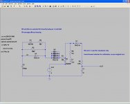
I slapped together an L meter for speaker range inductances. Not nearly the same league as this, but it fits in a tiny box somewhere near your DVM.
I got the idea from here:
Inductance Meter Circuit | Circuit Diagram
The "major" drawback is the test frequency and waveshape, but can probably get you within of a few percent of the number you want in any case. Pretty easily 1% if you're winding or modifying air core inductors.
The inverters can all be from one hex package, they're only different because I don't always use ltspice right.
Attachments
Last edited:
Oh. If anyone wanted to build that, I used 22uF for the real output filter. The little cap was just so the simulation would settle fast enough on my free computer.
Here is another DVM adapter for inductance. It's slightly more complex, but has a resolution of 10nH, can have up to 6 ranges, and has a decent rejection of minor parameters (mainly series resistance):
[En cours]Inductancemètre: la version jouet - Forum Projets électroniques
[En cours]Inductancemètre: la version jouet - Forum Projets électroniques
- Status
- Not open for further replies.
- Home
- Design & Build
- Software Tools
- An awesome ZLCR meter