Are you talking about this one?Hi Elvee, if there are no copyright issues, could you please attach the pdf from your link here ?
That forum requires registration to view the pdf, and the registration page is in french (and I don't know french).
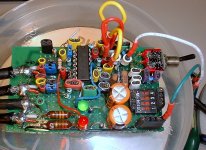
And here is my version of the ZLCR meter (fully configurable).
Attachments
Elvee, is your ZLCR meter using soundcard? If so, which software works with it?
I must say I am impressed about mine, now that is in the box and layout cleaned up. Very stable, consistent and accurate, does not get thrown out of balance with switching back and forth between C and L. I did not use voltage converter as I hate to see yet another cable going to the PC, I simply inserted 9V battery in the box with virtual ground.
I must say I am impressed about mine, now that is in the box and layout cleaned up. Very stable, consistent and accurate, does not get thrown out of balance with switching back and forth between C and L. I did not use voltage converter as I hate to see yet another cable going to the PC, I simply inserted 9V battery in the box with virtual ground.
Elvee, is your ZLCR meter using soundcard? If so, which software works with it?
It works with the visual analyser.
I noticed yet some other quirky behaviour: it seems difficult to measure high quality inductances, because when the total voltage across the component is too small, it indicates underrange, even though the value is well within the range.
A work-around is to add a resistance in series with the coil, but it's not very elegant, and it certainly degrades accuracy.
The tare function seems to work very erraticaly: at times, it is unavailable, with the button grayed out, and other time, when it works (sort of), the tare value is completely random and changes each time you refresh it.
Not sure what you mean by "high quality" inductors. Low parasitic resistance? I was measuring air cores (2mm wire) and ferrite bell core (1.4mm) ones, all spot on; 0,82mH and 1.80mH respectively.
I have seen random graying out of the buttons too, so that's a bug. Also, it seems to refuse to attach itself to non-default Windows sound device.
Yes: I tried to measure a 56µH inductor using a 10ohm reference resistor, and it indicated underrange, even though the permitted range under those conditions is 10µH to 10mH.Not sure what you mean by "high quality" inductors. Low parasitic resistance? .
Elvee
Have you tried to fiddle with the zero tare? I mean 56 uH is not much. I have not my unit connected ftm. but I will test this next time. 🙂
Have you tried to fiddle with the zero tare? I mean 56 uH is not much. I have not my unit connected ftm. but I will test this next time. 🙂
I did try, but one time it's 0.000µH, the next time 0.3154µH, then 0.3462µH.....Elvee
Have you tried to fiddle with the zero tare? I mean 56 uH is not much. I have not my unit connected ftm. but I will test this next time. 🙂
it seems completely random.
I've also noticed something else (not in the ZLCR): the frequency values in the spectrum display are incorrect: the fundamental at 1KHz f.e. is OK, but the harmonics are shifted, and the higher the harmonic, the larger the shift is: 150Hz at 2KHz, 300Hz at 5KHz, etc. Strange.
Asking for to much?
Elvee
I think you should mail the author about the bugs, fe. the frequency shifts. He will apreciate it. The software will be better further on.
I guess the zero resolution is not better then + - 1 uH. 1 uH is nothing. Just about two straight wires some centimeters long. If you want better specs you can't use the USB PSU and that simple circuit i refered to. In professional equipment, measuring such low values, you will have to pay a fortune to get stable measurings at 1uH resolution. I haven't even layed my hands on such expensive equipment, even though I work as a Metrology engineer, calibrating instruments at a petrochemical industry.
If you for example measure caps and have zeroed the unit with the box and the inbuilt short cables to the lab conectors and then connect your measuringcables, you see the capacitance changing when you bring the cables together or apart.
It's easily between 10 to 60pF just between the cables without any cap connected.
Hm, tried to measure speaker resistance, and it was wildly off. DMM measured 3,9ohm, ZLRC: 14,2 ohm...
DMM measure with DC
ZLRC measures with 1kHz or.... what frequency did you use? There are allways valleys and peaks in the impedance curve on a speaker trough out the 20-20khz range.
Your readings could probably be correct.
Please try to "read up" a bit on impedance, inductance, reactance and resistance.
ZLRC measures with 1kHz or.... what frequency did you use? There are allways valleys and peaks in the impedance curve on a speaker trough out the 20-20khz range.
Your readings could probably be correct.
Please try to "read up" a bit on impedance, inductance, reactance and resistance.
Measured with 1KHz, and I am not talking about reactance, just plain resistance. Should not that be the same regardless of frequency?
Not on a speaker, it's not a purely resistive load. If you are using AC (1KHz) then you are measuring impedance, not DC resistance.
That why the DCR and nominal impedance specs for a driver are different.
That why the DCR and nominal impedance specs for a driver are different.
No, it shouldn't, because it's a true vector measurement (I know, it's a bit puzzling).Measured with 1KHz, and I am not talking about reactance, just plain resistance. Should not that be the same regardless of frequency?
A speaker has huge iron losses (and also some mechanical losses, some of which are converted into sound).
These losses are parallel losses, but when they are converted, the series model (remember, this is all virtual) shows an increase in the series resistance.
Let us try to make it simple: the reactive impedance of your element is the pivotal value; let us say it is 10 ohm.
If you add a physical resistance of 1 ohm in series, it will translate into 100 ohm in parallel (ratio of 1 to 10 translates 10 to 1), and conversely, 100 ohm physical in parallel is equivalent to 1 ohm in series.
Things are more complicated than that, and the rule outlined is only valid when the losses are small compared to the reactance, but it shows the general behaviour of these parameters.
The basic rule is: you can never equate the losses of a reactive element to a single invariant resistive element.
Within limits, I found the ZLCR meter to operate reasonably on this aspect.
Radioman:
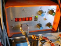
1µH isn't nothing: one of my home-made inductance meter has a resolution of 1nH at 100Hz (100fH at 1KHz), yet it isn't a lab instrument (except for my own lab).
But of course, with a sound card the limit is 16bit, which is rather crude compared to an instrument having a fully analogue front-end.
more then 16 bits
Elvee
What is "100fH at 1KHz" ?
I don't believe you in "1nH at 100Hz" in resolution, I'm sorry, I do not have trust and believe in those figures... period.
How do you f.e. null the measuring device with such resolution? Is it a work of your own?
Can you mention a single instrument in the world with more then 24bit resolution that you can trust on? More then a soundcard, which is, hands down, the most higly resolutet measuring device there is out there, at least for money in the ballpark of us living dead.?
Last edited:
Elvee
What is "100fH at 1KHz" ?
I don't believe you in "1nH at 100Hz" in resolution, I'm sorry, I do not have trust and believe in those figures... period.
How do you f.e. null the measuring device with such resolution? Is it a work of your own?
Can you mention a single instrument in the world with more then 24bit resolution that you can trust on? More then a soundcard, which is, hands down, the most higly resolutet measuring device there is out there, at least for money in the ballpark of us living dead.?
There is a typo, but it 's too late for editing.
But it isn't about the 1nH 100Hz, which is fully correct. I meant 100pH at 1KHz, not 100fH (I have also built a femtofarad-meter, which is why I was confused)
An HP3458 has 8.5 digit, which is over 27bit, and unlike your 24bit, they are fully exploitable (within certain conditions, of course).Can you mention a single instrument in the world with more then 24bit
My humble inductancemeter has a resolution of 1nH @100Hz but it is far from a 24bit equivalent: it only has 5 digits.
It is difficult to compare these kind of things: a good old analogue bridge has no digits or bits at all, yet it is capable of resolving microvolts or even nanovolts, and nanohenries or picohenries of inductance.
It is obviously a permanent 4W device, and before any sensitive measurement, a null has be performed.How do you f.e. null the measuring device with such resolution? Is it a work of your own?
It is far from a very high tech or sophisticated instrument, it is based on synchronous measurement techniques.
I'll try to make a scan of the schematics one of these days, if i'm able to locate them.... Not a big issue, really.
Here is already a pic of the instrument in action.I don't believe you in "1nH at 100Hz" in resolution, I'm sorry, I do not have trust and believe in those figures... period.
The schematics will follow (I hope) one of these days.
Attachments
Anyway, it seems that the same jig used for zlrc can be used for Limp and speaker parameters measurement. Great stuff!
The Visual Analyser seems to be an interesting software.
Does anyone know an open-source software with the same functionalities ? The one that I'm interested in is the impedance computation at different frequencies.
Does anyone know an open-source software with the same functionalities ? The one that I'm interested in is the impedance computation at different frequencies.
This seems a fantastic new contribution to the DIY art!!
I reckon I'll give this a shot when I get the next break from customers work..... Many thanks to it's author/programmer. I'm hoping that the next revision of the software will resolve the bugs and issues 🙂
Meanwhile, maybe one of our Italian members with too much time on his hands may care to translate for us all?
- Status
- Not open for further replies.
- Home
- Design & Build
- Software Tools
- An awesome ZLCR meter