Thanks for the input and tips, Bauhausler! Pentodes are certainly on the drawing board still.
I did try loading the secondaries with different values of resistance; 20K down to 6K. I could certainly see the effect on scope. But it didn't get rid of the distortion when the tube's suck current.
I could try a beefier chip amp. I needed more swing anyway.
I'll start tinkering with the amp in September. I finally have work in the studio now (!!) and our camp planning for Burning man has begun.
Wavebourne- thx for the offer on yr GU-50's to go to the playa. The thing is they might get trashed (by the weather and dust) and I'd feel REAL BAD if they broke!!
-Kent
Wavebourne- thx for the offer on yr GU-50's to go to the playa. The thing is they might get trashed (by the weather and dust) and I'd feel REAL BAD if they broke!!
In such case I can donate to Burning Man a couple of 6J51P tubes for drivers.
Whatever driver this output stage uses is going to have to be direct coupled to provide the grid current for the positive swing. There are several schemes for doing this in Class B PP tube amps. One of the simplest is the Altec 1570B driver. A center tapped choke is used as a load for 2 6W6 configured as cathode followers. The cathodes are direct coupled to the output grids and the choke center tap goes to the negative 'bias' supply. The CFs of course have no gain so they'll need a ton of drive voltage, the 350VPP that the output tubes require plus their G1-K signal, so probably nearly 400V p-p. For a center tapped choke you could experiment with the primary of a PP OPT, but 2 separate windings (for output stage bias balancing) would be better. That much voltage swing would be available from your 550V + rail. Something like a 12BY7 with resistive load should work as a voltage amp. Then a phase inverter/input stage like a LTP ahead of that. I have no idea if that's optimal but it looks OK on paper.
Yeah, what he said...
Elliano's scheme with a chipamp and high ratio step-up might work for squeezing 3db more out of a 300B but it won't cut it for a real power grid tube. The problem is going to be DCR of the transformer if nothing else.
Direct Coupling with a low impedance device like a voltage follower using a high gm tube or MOSFET is the only way to avoid the kink.
I would retrofit a MOSFET follower (see tubelab Power Drive) between the stepup and power grid and be done with it.
Cheers,
Michael
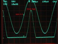
PS a follower arrangement (stacked mu-follower) for power grid drive, and the grid voltage at 300VP-P (top) and grid current at 50mA peak. No kink.
Elliano's scheme with a chipamp and high ratio step-up might work for squeezing 3db more out of a 300B but it won't cut it for a real power grid tube. The problem is going to be DCR of the transformer if nothing else.
Direct Coupling with a low impedance device like a voltage follower using a high gm tube or MOSFET is the only way to avoid the kink.
I would retrofit a MOSFET follower (see tubelab Power Drive) between the stepup and power grid and be done with it.
Cheers,
Michael
PS a follower arrangement (stacked mu-follower) for power grid drive, and the grid voltage at 300VP-P (top) and grid current at 50mA peak. No kink.
Attachments

Michael, what's the deal with Q3, random (part selection dependent and temperature dependent) bias voltage generator ?
Michael, what's the deal with Q3, random (part selection dependent and temperature dependent) bias voltage generator ?
It's called surprise bias ;-)
No, seriously, the Vgs of these are amazingly stable and consistent, and have pretty low impedance. It makes a nice 2.8V diode. It's also a great conversation starter.
I suppose a boring old TL431 would work even better but I was out of them and this is what stuck to my hand coming out of the parts box.
Q2 is more of a drift problem and if I built this amp in a box I would come up with a more stable generator and a series 220K resistor...
Cheers!
Michael
Last edited:
I would expect 2N7000 to be faster than boring TL431.
Faster for me.. I didn't have to wait for Mouser and the USPS 😛
6SN7s work pretty well for large voltage swings. I have been getting just over 1% distortion at 200Vrms(almost 600Vpk-pk). I used CCS load and 800V B+, AC coupled to FQPF2N90 source follower. Follower drives the grid current just fine and 6SN7s are very happy with nearly infinite load. Much cheaper and better than a transformer, in my opinion and would be able to drive almost any output tube you choose.
6SN7s work pretty well for large voltage swings.
I have seen the same thing. Best results are achieved with a CCS load into a mosfet follower (PowerDrive). I have also used them in LTP with a CCS in the tail and a resistor load into a mosfet buffer. I haven't been to 800 volts vet, my power supply only goes to 650 V. Not all 6SN7's are created equal, some work better than others, especially on big voltages. Unfortunately the best ones that I have are the uber expensive red RCA 5692's.
Faster for me.. I didn't have to wait for Mouser and the USPS 😛
I have fat ziplocs with both in my barn; I mean 1 (one) FET vs 3 emitter followers + 2 current mirrors + 1 cascode + and 20 pF capacitor shunting low current high dynamic resistance thingy.
I was using the new production Tung-Sol 6SN7s for my tests. I have some other 6SN7s to try but power supply broke and can't be fixed until other things are paid for.
No, seriously, the Vgs of these are amazingly stable and consistent, and have pretty low impedance. It makes a nice 2.8V diode. It's also a great conversation starter.
Ooo, I didn't know that - I have a bunch of these sitting somewhere in my stash, I should give them a try I suppose, I'll have to dig them out first though 🙂
Thanks for the tips and schematics, chaps. I've never done a source follower, I'm looking forward to fiddling with them in the future.
I liked the idea of an interstage transformer mainly to reduce active components in the circuit. But transformers fail, too. Easier to replace a blown mosfet than winding a transformer in the desert.🙄
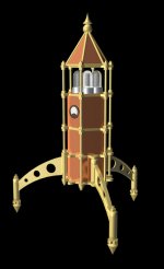
Attached is a 3D model I did a while ago. A hexagon tower, ~ 3' high. Stacked chassis. I have the legs (from an old golf display stand). Originally all SS drive, it's now too skinny for more tubes.
Just a shape concept for now. It would look cool with tungsten fil. tubes!
I liked the idea of an interstage transformer mainly to reduce active components in the circuit. But transformers fail, too. Easier to replace a blown mosfet than winding a transformer in the desert.🙄
Attached is a 3D model I did a while ago. A hexagon tower, ~ 3' high. Stacked chassis. I have the legs (from an old golf display stand). Originally all SS drive, it's now too skinny for more tubes.
Just a shape concept for now. It would look cool with tungsten fil. tubes!
Attachments
Hi Kent
It's really great to see your creative steampunk design juices flowing again!
Where are all the knobs and levers, is there a hidden secret door? maybe some knife switches for the filaments.
Perhaps use HexFet audio modulation to the filaments for a light show? You have seen Nelson Pass's Class A lightbulb design at burning amp.
Steampunk!
I'd love to make a Steampunk tube amp and may some day. But my design skills are weak. Circuits, OK. Aesthetics not so much. My latest amp interpretation is the LM1875 build project for Make Magazine in plain alu and plexi. They're selling the active circuit as a kit and I really hope someone goes nuts with it design-wise.
I'm working on another amp project for them now and it will involve the odd and lovely GU-50 pentode. I doubt the cosmetics will rise above the mundane. Magazine pages are costly and I'd rather talk about tube technology than give step-by-step instructions for metalworking.
Thanks for the tips and schematics, chaps. I've never done a source follower, I'm looking forward to fiddling with them in the future.
I liked the idea of an interstage transformer mainly to reduce active components in the circuit. But transformers fail, too. Easier to replace a blown mosfet than winding a transformer in the desert.🙄
Attached is a 3D model I did a while ago. A hexagon tower, ~ 3' high. Stacked chassis. I have the legs (from an old golf display stand). Originally all SS drive, it's now too skinny for more tubes.
Just a shape concept for now. It would look cool with tungsten fil. tubes!
You can use the existing transformer for voltage gain AND source followers to power the grids. just put the source followers between the transformer secondary and the output tube grids. You'll also need a negative voltage and pull-down resistors. Stopper resistors on the MOSFET gates and zener diodes to prevent going over +15V gate-source.
IMO this would be a quick and simple way to get the "kinks" out of your current circuit operation.
Cheers,
Michael
Baupunk? Steamhaus?
chip and transformer as high voltage driver
This is somewhat OT but I wanted to validate that the chip/transformer driver works for class A1 situations.
For a circuit I'm working on I needed up to 150VRMS of clean drive signal so I adapted the concept of the chip amp and step-up transformer for testing. I used a LM1875 chip to drive the secondary of a 25:1 SE OPT (Edcor 5K:8Ohm). At 150VRMS/1kHz out of the chip/transformer driver my test rig* measures just 0.05% THD + noise, much of which is certainly residual THD + noise of the distortion meter and sig gen.
This works great for testing output stages, as it removes the influence of the driver stage and allows you to concentrate on the parameters of one stage at a time.
I'm running the 5K side of the transformer unloaded at this time, but it peaks badly at 50 KHZ so it needs some damping to be used up there. I'm testing with sine at 1kHz right now so I don't care about that.
Now from a single KT-88 I'm getting 0.9% THD at 12W output.
365V plate and screen
-33V bias
83ma (30W total diss)
3700 Ohm load, 60% plate, 40% cathode
110VRMS drive signal for 12W out.
That's pretty great performance but the fly in the ointment is getting triple digit drive voltages with low THD. I have some high Gm 5W - 10W pentodes to test that should do the trick off of a supply of 500V or so. 6P9 gets me close (2% driver THD at 110 VRMs off of a 400V supply) but I think I'll have to go up to 12GN7 with 250V on the plate to get more swing.
* HP 200CD sig gen and 331A THD meter. Very old gear but cheap, reliable, easy to use and plenty accurate for tube amp work.
Last edited:
- Status
- Not open for further replies.
- Home
- Amplifiers
- Tubes / Valves
- An amplifier for Burning Man