....
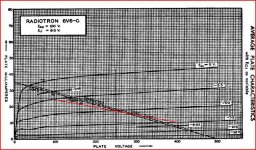
Now from a single KT-88 I'm getting 0.9% THD at 12W output.
365V plate and screen
-33V bias
83ma (30W total diss)
3700 Ohm load, 60% plate, 40% cathode
110VRMS drive signal for 12W out.
Sure, if there's little to no grid current beig sourced, the stepup transformer can work well. Jack Elliano's 300B amp sounded pretty good at VSAC.
But the question on my mind is how you are getting a single KT88 to eat over 300 volts peak-peak grid drive with only -33V bias. Cathode feedback perhaps?
Cheers,
Michael
But the question on my mind is how you are getting a single KT88 to eat over 300 volts peak-peak grid drive with only -33V bias. Cathode feedback perhaps?
3700 Ohm load, 60% plate, 40% cathode
I think we called it distributed load, twin coupled, or maybe just "the McIntosh circuit"
There was an article in a magazine a while back that used two OPT's, one in the cathode and one in the plate. Needs big bunches of drive voltage.
I think we called it distributed load, twin coupled, or maybe just "the McIntosh circuit"
There was an article in a magazine a while back that used two OPT's, one in the cathode and one in the plate. Needs big bunches of drive voltage.
Aha, that's what the 60% and 40% refer to, where the actual plate load Z is pretty low and there is effectively 2/3 of the output fed back to the cathode, assuming turns 60/40 ratio is specified. If so you need to drive 2/3+ of the plate-plate signal into the output stage...
Mac bootstrapped the drivers with another transformer winding to get that huge swing if I remember right.
Something I've always wondered is when does it stop being cathode feedback and start being "twin coupled" ? And does the OPT winding design for coupling have a lot to do with it?
Sure, if there's little to no grid current beig sourced, the stepup transformer can work well. Jack Elliano's 300B amp sounded pretty good at VSAC.
But the question on my mind is how you are getting a single KT88 to eat over 300 volts peak-peak grid drive with only -33V bias. Cathode feedback perhaps?
Cheers,
Michael
Yup. Modded OPT for separate windings. Call it Modified Ultralinear if you want to honor Crowhurst, although his was PP. I think Schade was on to this as well.
I've been fooling with drivers today (92 degrees outside, nice and cool down in the shop). The best THD I can get out of one is 2% at 110Vrms. That's a Russian 6J52P (supposedly like PL802) running a 520V supply. 260 on the plate, 180 on G2, 8800 Ohm load, 29 - 30 ma. I haven't checked the gain, but with the screen that high I'm sure there's lots of degeneration from Rk.
That's 7.5W total, diss, 700mw of it is G2.
The real beauty of the modified UL output stage scheme is:
Eg2 does not have to equal Ep
the Zout is 1 Ohm or less.
drastically low THD
The beast is:
takes a ton of drive voltage.
Something I've always wondered is when does it stop being cathode feedback and start being "twin coupled" ?
Never, actually.
Aha, that's what the 60% and 40% refer to, where the actual plate load Z is pretty low and there is effectively 2/3 of the output fed back to the cathode, assuming turns 60/40 ratio is specified. If so you need to drive 2/3+ of the plate-plate signal into the output stage...
Mac bootstrapped the drivers with another transformer winding to get that huge swing if I remember right.
Something I've always wondered is when does it stop being cathode feedback and start being "twin coupled" ? And does the OPT winding design for coupling have a lot to do with it?
Crowhurst's Twin Coupled amps used separate OPTs for the cathode and plate sections. It was PP and had funny looking coupling between primaries.
Bootstrapping (also used by Crowhurst) only works in bipolar amps. In SE you just have to generate the whole drive.
I'm finding that the drive voltage (40% of total swing plus grid to cathode signal) is turning out to be 53% of total swing most of the time.
12W into 3700 Ohms = 230VRMS. I need to drive 111 VRMS into the stage to get that out.
***EDIT***
Sorry for dragging this OT. I wanted to comment on using the chip/transformer driver scheme & got carried away.
Last edited:
Crowhurst's Twin Coupled designs just used two identical OTs, which gave 50% CFB. One could use different OTs to get less % CFB, but the 50% case is special in that you can cap. (electrolytic) cross-couple the cathode and plate windings together to get the same tight coupling Mac got with the bifilar windings.
The one minor weakness of these approaches (Twin C, CFB, even Mac) is that the cathode to plate windings for each tube are not coupled any better than in average designs. Not a big deal though, since each tube drives both sets, but it means that the OT is not taking full advantage of all the internal primary to secondary leakage Ls in parallel at any given time (in class AB or B).
Circlotron goes the whole 9 yards, using all windings 100% efficiently. Elliptron goes 8 yards and will do 28.57 % CFB using the UL taps on a single ordinary 40 % UL OT. (tube plates go to Pl connections., cathodes to UL conns. thru elect. caps, a CT inductor supplies the actual DC to the cathodes.)
The higher the % of windings used by each tube, the lower the leakage L (to secondary) for the OT. Most OTs only use 50% of the primary at a time (class B mode). Elliptron uses 1.4/2 = 70%
Circlotron uses 100%. Mac uses 50 % or 100 % depending on how you want to consider the bifilar coupling, but the presence of doubled up primary windings still increases leakage L to the secondary simply by taking up extra space on the bobbin. The Twin Coupled only uses 50% of each OT at a time, but with 2 OTs, it effectively halves the leakage L. Can think of it as doubled up interleaving or sectioning effectively.
Last edited:
Interesting take on the magnetics issue. I'm dealing only with the SE case at this time for simplicity. I understand that in PP OPTs with CFB or tertiary windings one difficulty is getting the resistance and the ratio of the cathode windings correct, as slight imbalance leads to higher THD.
Yes, agree. A high quality CFB P-P OT would need to use at least a split bobbin to get DC resistances and leakage Ls the same for each tube. DC resistance imbalance on mediocre OTs should be fixable though with a compensating resistor.
Fortunately (for Elliptron anyway), the UL sections of the usual OTs are usually located in the winding buildup at the mid point between two secondary interleaves, giving the best coupling, and fair leakage L balance. UL feedback mode needs these sections matched too. The center tapped DC cathode-feed inductor for Elliptron mode can be designed for tight coupling between sides also (so equalizing couplings).
Twin-coupled would be more likely to have some significant imbalance in coupling using mediocre OTs, since it is using the outer most primary interleaves as well ( as the UL sections) for the CFB windings. In theory at least, the twin coupled, with the cross-coupled electrolytics, nulls this imbalance out though, since each cathode will be tightly coupled to an OT side A and side B. Effectively doing the split bobbin across the two OTs. They better have the same steel and be turns # identical and truly center-tapped of course.
May still have to add some HF tweek to the P-P drivers to counter un-balance the drives to compensate the OT imbalance at high Freq.
Last edited:
I should note that going Elliptron mode does double approximately (1.4 * 1.4 for 40% UL) the effective primary Z of the OT. So does Twin-Coupled of course. But Twin-C uses the 16 Ohm secondaries in parallel to get an 8 Ohm output. The Elliptron still has the option of using the 16 Ohm secondary for 8 Ohm drive output to re-normalize back to the original primary Z if 2X Zpri is not wanted. Then again, the Twin-C can develop twice the power transfer using two OTs, so 2, 4, and 8 Ohm outputs (4, 8 and 16 Ohm paralleled) at twice the power make perfect sense.
Last edited:
Crowhurst's Twin Coupled amps used separate OPTs for the cathode and plate sections. It was PP and had funny looking coupling between primaries.
Bootstrapping (also used by Crowhurst) only works in bipolar amps. In SE you just have to generate the whole drive.
I'm finding that the drive voltage (40% of total swing plus grid to cathode signal) is turning out to be 53% of total swing most of the time.
12W into 3700 Ohms = 230VRMS. I need to drive 111 VRMS into the stage to get that out.
***EDIT***
Sorry for dragging this OT. I wanted to comment on using the chip/transformer driver scheme & got carried away.
I see, calculated on total swing it's 40% plus the grid-cathode swing.
What about an EL84 or even a 6V6 for your driver?
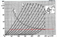
Whatever tube, you might try at about 250V with a combination resistor and CCS load to get a high flat load line. You don't necessarily want to swing a lot of current. For example, a 6V6 with 20K load in parallel with a 10mA CCS, 400V B+ would easily swing 110VRMS. If you needed lower impedance you could use a higher gm tube. If you needed more linearity, you could use a higher gm tube with an unbypassed cathode resistor.
I'm playing with drivers myself today. I'm using a 6V6 at 150V on the plate and getting about 240V Pk-Pk swing at clipping. I only need about 120V pk-pk today, for a Schade-feedback G2+G1 drive amp using sweep tubes, but I want some headroom for later. I'm using a gyrator which has a high AC impedance to set the plate voltage and a 10K ohm test load to simulate the Schade feedback. I haven't measured the distortion yet and will probably plug in the sweep tubes now that I have the driver debugged.
Cheers,
Michael
PS the load line below is what I'm proposing for about 110VRMS swing. It would need another 30V B+ or so to cover the CCS Vds
Attachments
Last edited:
I'm trying to get my 110VRMS drive off of a line level signal, which means I need a stage gain of around 70. This means really high Gm, and a 6V6 wouldn't do it.
This is where I am at the moment, but if I can't get the driver THD down under 1% @ 110vrms with a gain of 70 I'll resort to a lower gain driver and add a stage.
I have a few more tests to run before I've exhausted the options for a single-stage driver. It's a lot to ask of a driver, but if I can figure it out a 2-stage amp will be preferable to 3-stage. A neater, more elegant solution. Too often I see amps with anode loaded triodes just stacked 3 and 4 deep and wonder if the designer actually looked at the gain structure that was needed or just lined up their favorites.
**edit**
I just put my glasses on and had a look at the 6V6 loadline above. Maybe that would work. Gotta sling that together tonight & see how it measures.
Last edited:
6V6 as driver
Itried out the 6V6 as a driver today.
B+: 600V
Rl: 20K
Rk: 220, unbypassed
Eg2: 110V
Ep: ~245V
Ik: ~0.020
Gain: 44 (exactly where I need to be)
The THD at 110vrms was 2%, exactly what I got from the 6J9 and 6J52 tubes. The 6V6 did get all the way to 170vrms before it clipped (5% THD) so that's better. The smaller tubes clipped at around 130Vrms.
2% THD isn't really bad, but since the output stage is only contributing 0.9% at that level I'd like to find a way to do a little better.
I suppose I could try raising Eg2 and Rk and rely on the extra degeneration from the bigger Rk to linearize things, but then I'd be giving up gain.
Maybe a 6BQ5, but I kinda see a pattern here...
There might be some distortion cancellation to be exploited between the driver and output tube, but if you want to do better I think you'll need to go to a super-gm tube like a D3A or 12HL7, etc. The attached loadline is for a triode-connected D3A with a CCS in the anode circuit that would swing 330V pk-pk at pretty low distortion. I think if I didn't need a pentode for any particular reason this would be a good way to go. I don't show the load of the grid gresistor for the next stage, but if you are driving significant load you can tap the output at the MOSFET source for lower impedance.
I did a similar thing with a 5842 that would swing 300V P-P at close to 1% distortion to drive a transmitter tube in triode mode whilst sourcing 50mA of grid current; the D3a would give you a little more voltage headroom and with cap coupling a CCS would be a simple way to get huge linear swing.
Michael
PS I just thought of another way but 2 stages of DHT with anode chokes is probably not what you had in mind...
Attachments
Last edited:
Thx for the responses. I have some IXYS CCS chips on order and will try the CCS triode option. I have other pentodes like 7788, 12Gn7, 8233, 12BY7, etc. on hand to try out.
The 6J52 shows promise as well. I have 5842 on hand, but those are so scarce I really don't want to marry a design to them.
I want to get the driver THD under 1% at 110vrms and I think that's doable.
The 6J52 shows promise as well. I have 5842 on hand, but those are so scarce I really don't want to marry a design to them.
I want to get the driver THD under 1% at 110vrms and I think that's doable.
I've done a little fooling with the CCS* loads and the Russian driver pentodes. I made up a little board for the CCS with screw terminals for in and out, a trimpot for current adjustment and a heat sink.
First test was a Russian pentode, the 6J52P. This is a $5 10W unit (Gm = 50,000 - 60,000 in Pentode).
I triode strapped it and ran it with the CCS off of a 400V supply. It seems to like 7.5 to 12 ma of current and 210 - 240V on the plate. Not really fussy. Anywhere in there gives you 110VRMS out with THD at 0.85% to 1%. That should be pretty easy to set up, as the CCS has about a =/- 5% tolerance on the current for a particular setting resistor. Shoot for the middle (say, 9.5ma) and use a trimpot in the tube cathode to set the Ep to around 220V and you're done. I shifted the driver current and plate voltage around by 20% and the THD never goes over 1.5%, which is still reasonable. This will not be tweaky for someone without a THD analyzer to set up.
The gain is an amazing 73 (1.5V in for 110V out). That may go down when it's swinging current into a following grid resistor, but that's OK. Gain of 44 or better is what I need. A 6SL7 certainly won't give you THD that low at 110V.
So there it is. A driver that consumes less than 4 watts total (15% of the output stage's power consumption), and has THD equal to the output stage (just under 1% for each stage). And the whole shebang, both stages, runs off of a 400V supply. No screen supplies or bias supplies.
It could hardly be simpler than that.
I'm particularly pleased with the low power consumption of the driver. There are lots of ways to get low THD high voltage swings but most of them waste a lot of power that doesn't contribute to output production and that seems like inefficient design.
Next I want to try this with the smaller and cheaper ($2) 6J9P (3W plate, 16,000 pentode Gm) and see if I get similar results. The smaller tube seems to be very common and is cheap all over.
Also I'll try different following grid resistors and see how that affects THD. I tried a relatively severe 75K following grid R and the THD at 110V went from 0.85% to 1.4% but that's a pretty extreme condition and still not out of range. It's possible that altering the operating point would compensate for the AC load somewhat.
I also want to test the CCS' DC overhead and AC resistance at various current levels. Overhead looks like 10V from the spec sheet but I'll check.
*IXCP10M45S
Thanks for the info and experiments, folks. When I have time after this years' burn, I would like to try the some super-gm tubes with a CCS load. I would need to find a suitable interstage/splitting transformer. Then, as Michael recommended; source followers to the grids of the output tubes.
I'm deep in planning mode for the burn, so not too much will come from me till after.
-Kent
I'm deep in planning mode for the burn, so not too much will come from me till after.
-Kent
Here's some more testing on cheap drivers.
I tried the Russian 6J9 tube in the driver setup because it has the same pinout as the 6J52 & I didn't have to change the socket.
It has a Pdiss of 3W and will run well in triode at 200V - 250V. Gm is said to be around 16,000 in pentode mode.
Here's the best test:
B+: 400V
Ep: 220V
Ik: 5ma
Ek: 4.2V
input: 3.0V
THD @ 110 v out: 0.62%
It seems to like currents from 4 to 7 ma and plate voltages from 200 - 240. It's a pretty broad range where the 110V THD is below 0.7%. Above 240v plate, the load runs out of voltage headroom when swinging 300V P-P & strange clipping appears.
The gain is a bit low: about 35. I can't get it to go up at all. The higher Gm 6J52 (50,000) had a gain around 73 in triode mode which is more than I need. 40 - 50 is about right.
I should try some tubes over the 20,000 Gm range & see what happens.
0.62% is pretty low THD at 300V p-p and I don't know if I can do better although I'd like to see a $1 - $2 tube do 0.5% with less than 2W diss. This whole driver circuit dissipates 2.5W, less than 10% of what the power stage does, which is acceptable. The tube costs $2 new and the CCS load costs $2, so I can't argue on price.
I'll build another test socket and try the 12GN7 and 12HL7 next.
- Status
- Not open for further replies.
- Home
- Amplifiers
- Tubes / Valves
- An amplifier for Burning Man