DSP in every cabinet brings new options
Hi Binely,
Thanks for the thumbs up!
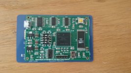
We are putting our DSP board inside every active speaker (not in the passive ones) & when combined with WiSA opens up a new world of possibilities ....Smart loudspeakers that can "talk" to one another and alter parameters to suit location and audience....
Touring as well as fixed venue locations vary in acoustics, even cinemas acoustics change from almost empty to having 1,000 bodies in there....
I have attached a pic of the prototype board and we are now upgrading the DSP chip to this TMS320C6748 | C674x Low Power DSP | Fixed/Floating-point | Description & parametrics
and the software and functionality is an upgraded version of the Signal Wizard 3 system here Signal Wizard 3.0
Happy to brainstorm and listen to suggestions as we will be releasing a version of the DSP with an electronics pack to the custom install market and a version to the DIY community.
Cheers
Derek.
*Derek, just read your post above and it looks like a lot of what I just typed below was part of your prior art. Apologies - but will leave them below as a "Thumbs Up". Bravo.
Am I reading this right - the idea of discrete dsp's in the unit? I wonder if they could even be made to "talk" to each other if you were using wireless technology anyway - master clock and all.
Perhaps with the right implementation, a setup mode could be used to have them calculate the distance/time between them to setup some sort of check bit system in the clocking that is only intermittently confirmed through a signal in the "noise" spectrum.
In a non-ideal placement what of a reinforced "mono" mode instead of stereo. The two channels could be combined, with one monitor primary, the second one fill in.
Ooh I love a good rotary encoder...
Hi Binely,
Thanks for the thumbs up!
We are putting our DSP board inside every active speaker (not in the passive ones) & when combined with WiSA opens up a new world of possibilities ....Smart loudspeakers that can "talk" to one another and alter parameters to suit location and audience....
Touring as well as fixed venue locations vary in acoustics, even cinemas acoustics change from almost empty to having 1,000 bodies in there....
I have attached a pic of the prototype board and we are now upgrading the DSP chip to this TMS320C6748 | C674x Low Power DSP | Fixed/Floating-point | Description & parametrics
and the software and functionality is an upgraded version of the Signal Wizard 3 system here Signal Wizard 3.0
Happy to brainstorm and listen to suggestions as we will be releasing a version of the DSP with an electronics pack to the custom install market and a version to the DIY community.
Cheers
Derek.
Attachments
Thermal compression in voice coils...
Hi Steven,
I think that thermal compression in voice coils is a huge issue and one that is often ignored, I know I ignored it until I read Michael's fantastic report ( attached) and it know helps shape everything I do with both driver and system design.
Second only to accurate time domain performance, maintaining thermal stability and avoiding impedance peaks is a high priority in my book.
Hope this helps
Cheers Derek.
snup,
I'm not worried about power compression at this point.
Richard two layers is really the norm for that very reason, it is easier. I think most compression drivers use a single layer rectangular wire. Actually I wonder if the second layer running in a counter direction does any cancelling if they are perfectly lined up?
Hi Steven,
I think that thermal compression in voice coils is a huge issue and one that is often ignored, I know I ignored it until I read Michael's fantastic report ( attached) and it know helps shape everything I do with both driver and system design.
Second only to accurate time domain performance, maintaining thermal stability and avoiding impedance peaks is a high priority in my book.
Hope this helps
Cheers Derek.
Attachments
tilting at windmills?
Yep, or barking up the wrong tree. Take your pick.
Yet you confirmed "correct" to my statement The transformer does NOT create extra power.
Nothing you've given in calculations have I disagreed with except the first claim that its 'impossible'. It may indeed be impossible (I may have overlooked something vital) but nothing you've said has so far come close to pointing out anything I've missed. Certainly no magic is involved and transformers don't have magical properties.
It seems to have started in post69.
The reply in post71 and your restatement in post72 are completely at odds with each other.
Using a transformer cannot possibly get 400W from two 50W or 60W chipamps.
Your claim that you can get 400W is what I said was impossible.
You are agreeing that, two chipamps in bridged mode can deliver twice the power into twice the load.
Adding a transformer cannot increase that.
The author got his basic assumption wrong in para10Hi Steven,
I think that thermal compression in voice coils is a huge issue and one that is often ignored, I know I ignored it until I read Michael's fantastic report ( attached) and it know helps shape everything I do with both driver and system design.
Second only to accurate time domain performance, maintaining thermal stability and avoiding impedance peaks is a high priority in my book.
Hope this helps
Cheers Derek.
he says:
"Obvious the resulting current flow through the voice coil for the same speakers terminal input voltage is dropping at around 35%..."
But it does not. The current is resisted by the speaker impedance plus the other circuit impedances including the amplifier output impedance.
The total impedance limiting the voice coil current is NOT solely the voice coil resistance.
Further on he gets it wrong again where:
"Heating up the voice coil is an immediate process - cooling down isn't" yet this was after showing us that the heating up is time dependent. It is not instant, just like cooling is not instant.
Last edited:
..... The current is resisted by the speaker impedance plus the other circuit impedances including the amplifier output impedance.
The total impedance limiting the voice coil current is NOT solely the voice coil resistance.
In an active system with drivers close coupled to the power amp outputs there are no "other circuit impedances"....
The effect of a correctly designed power amp with low output impedance will be minimal.....
Further on he gets it wrong again where:
"Heating up the voice coil is an immediate process - cooling down isn't" yet this was after showing us that the heating up is time dependent. It is not instant, just like cooling is not instant.
Again you are missing the point...
Its the ratio of heating time to cooling time.....
The voice coil heating time is almost instant when a power surge ( transient) hits the coil, the coil then takes much longer to dissipate the heat.
This effect then accumulates as the coil gets progressively heated faster than it can cool.....
Andrew - I think we all are excited for a lively discussion about a real implementation. What were your ideas?
Nobody is requiring a demonstration of understanding for a contribution at this point. A lot of brainstorming right now. Ideas can be vetted, proven unworkable as we go.
Best wishes! You are welcome here.
Nobody is requiring a demonstration of understanding for a contribution at this point. A lot of brainstorming right now. Ideas can be vetted, proven unworkable as we go.
Best wishes! You are welcome here.
Hi Binely,
Thanks for the thumbs up!
Happy to brainstorm and listen to suggestions as we will be releasing a version of the DSP with an electronics pack to the custom install market and a version to the DIY community.
Cheers
Derek.
Derek - Very excited to see a subject expert on the DSP side! As I get a chance I'll look over the links and see if I can get up to speed. Nice size chip! CC was a nice touch. 🙂
I have not read the whole pdf. It looks worth reading properly.
But it is disappointing that early in the article there are fundamental errors in basic presentation.
As for ideas, I have presented some of my thoughts and an example of where I did go in a similar Thread.
But it is disappointing that early in the article there are fundamental errors in basic presentation.
As for ideas, I have presented some of my thoughts and an example of where I did go in a similar Thread.
Andrew, if you transform the load to an optimum impedance point (load line anyone?) you can eke more power out of the chip, because it works at max voltage and max current at the same time.
With 4 or 8 ohms it either reaches max current before max voltage or vice versa.
Edit: if your hypothetical chip can deliver 5A pk and has a max supply range of 42V, and you load it with 4 ohms, you get 20V pk on the load and 49 Watts and that's the max with that chip in that circuit.
BUT, if you go to 8 ohms load, your 5A pk gives 40V pk on the load and that's 98 Watts.
I didn't do the details calculations but it may well be that for a 3886 the optimum is 12 ohms. Nothing magical.
Jan
Last edited:
The chipamp dissipation plays against trying to extract more than about 60W to 70W from the chipamp when driving a resistor test load.
That is not what I see as the problem.
It's the magical ability of a transformer to get 400W from a pair of 50W chipamps.
That is not what I see as the problem.
It's the magical ability of a transformer to get 400W from a pair of 50W chipamps.
Cable looms - is there a standard
At the risk of being off topic - where amps are external and designed for purpose I know that neutrik speakon connectors simplify and provide protection for active - amplifier hookup. But - for multiwire looms into banana type connectors is there a colour code / numbering or labelling standard that is multilingual?
At the risk of being off topic - where amps are external and designed for purpose I know that neutrik speakon connectors simplify and provide protection for active - amplifier hookup. But - for multiwire looms into banana type connectors is there a colour code / numbering or labelling standard that is multilingual?
As for ideas, I have presented some of my thoughts and an example of where I did go in a similar Thread.
You did, and you were corrected then. And now again you are presented with a text which doesn't conform to your preconceived notion and presto, here we go again. Well, not me, besides this post, it is the last time I an making an effort.
Thermal effects are real, they are considerable, and they do not only lead to compression, but also to non-linear distortion.
Last edited:
Just catching up with the conversation, have to sleep once in awhile.
On the subject of voicecoil heating, yes I am aware of it but the reality is that at normal listening levels, perhaps a couple of watts input into a 86db per watt output device I don't think we have any real issue to worry about. At high output with max input we can look at that. But I am using a voicecoil that is nominally rated at 150 watts power handling in a normal short gap design. The maximum output of this design will be in the range of 60 watts continuous power, this will be about 110db so plenty of output from a small driver. Other factors such as a full length copper sleeve in close proximity to the voicecoil and a very large mass of metal on both sides of the coil will help to dissipate the heat, transients should not be a problem.
I have destroyed one of these drivers but it was not from voicecoil failure, it was caused by the limited excursion of a 1/2 roll surround, full excursion caused the failure mode due to this physical limit. I am working on a solution for that, a longer excursion surround but that brings other issues to deal with. That is something I have been discussing when I have a chance with Richard Lee for those of you who know him.
Overkill,
I haven't had a chance to look at your little board but that looks very interesting to me. I will read what you put up and ask questions afterwords.
DSP and DAC implementation is all new to me. I was reading a bunch of notes on the TI site last night but I don't think perhaps they have the most elegant solutions, I am trying to play catch-up here on this subject.
One area that is out of my wheelhouse is the software used in these applications to control all of this and implementation of FIR filtering, time alignment, eq, xo and all the other bits we need to make all this work. And then there is the control of level, do you just leave that up to the source component or do you have a remote controlled volume, balance and other things in the digital domain inside a powered speaker or leave well enough alone and make all that fixed in the speaker? USB streaming from a computer source is one thing, but what of a memory stick where you have to select songs and convert that information on the stick to an analog signal, this can get complex if we add everything in the tool kit into a powered speaker.
I assume if we are going wireless that we need to make one of the speakers a master and the other a slave so we have a stereo system or is there a way that they can both be masters and communicate to each other which is which, I am only thinking that because someone may wants to add extra speakers and create a 5.1 or even a 7.1 system?
By the way, off topic, what ever happened to the 9.1 systems I read about in the past for movie theaters, adding two more channels to give height information to the front channels. did that ever happen and is it only for projection screens with coding on the digital masters theaters would get? I know way off topic but I keep wondering about that?
Overkill,
Do you have an idea of cost on that small dsp board and the added cost of adding the Wisa wireless system? I'm curious. You can send that information to my as a PM if you like.
Do you have an idea of cost on that small dsp board and the added cost of adding the Wisa wireless system? I'm curious. You can send that information to my as a PM if you like.
The chipamp dissipation plays against trying to extract more than about 60W to 70W from the chipamp when driving a resistor test load.
That is not what I see as the problem.
It's the magical ability of a transformer to get 400W from a pair of 50W chipamps.
Nothing magical - if you really read what was written you'll see that it is along the lines I wrote.
And he pulled a familiar trick - he said '400W peak'; that's how you can spec a PC desktop speaker with an external 15V 2A wall-wart as '200W peak' ;-)
Jan
Jan,
Thanks for visiting the thread and contributing you insight. I understood what Abraxalito was saying about peak power, not continuous power levels. I think by the time you are seeing those peaks out of a 3886 set of chips the "Spike" protection would have rear up and bit you on the behind. The chip may live but I don't think you want to hear that circuit kick in. There is a complete set of notes from the old NI days that tells you how to build a bridge/parallel circuit but the people I talked to in the past said the design had some major flaws and poor assumptions. That was a reason I moved away from that idea. It seems that most, even those that are very invested in monolithic chip amps agree that a discrete design usually wins in the end for sound quality.
Thanks for visiting the thread and contributing you insight. I understood what Abraxalito was saying about peak power, not continuous power levels. I think by the time you are seeing those peaks out of a 3886 set of chips the "Spike" protection would have rear up and bit you on the behind. The chip may live but I don't think you want to hear that circuit kick in. There is a complete set of notes from the old NI days that tells you how to build a bridge/parallel circuit but the people I talked to in the past said the design had some major flaws and poor assumptions. That was a reason I moved away from that idea. It seems that most, even those that are very invested in monolithic chip amps agree that a discrete design usually wins in the end for sound quality.
Jan, exactly. I don't understand on what factual basis he disagreed with you. Peak is peak, RMS is RMS. What is the problem here? I see no reason for hashing out something that is over and done with.
As far as the volume pots on the loudspeaker, I would think that would be done digitally through the DSP and DA stage. Most DA have a variable output available in the datastream that come through from the wireless connection. I've used it quite a bit in basic phone to headset BT connectors.
Of course I'm coming from my point of view but if you have analog source, then there is a matter of source volume and then volume set by the transmitter so that would be up to the user. For a usb drive that would have to be set at the point of reading, so that would be at the "base" For USB/SPDIF that would be again controlled by the source - for example, I have a phone that controls spotify on my computer which streams digital encoded audio to the DAC which uses the volume level specified by the stream. In a block diagram the only time the "base" would have to be the sole volume attenuation is if you used a USB connected device Samba share or similar UPnP connected share where it is directly reading the file.
At the risk of sounding repetitive, in the example above the gain would be fixed in the speaker itself, we would just be attenuating the amplification level at the small signal level at the DA stage.
Jan,
Thanks for visiting the thread and contributing you insight. I understood what Abraxalito was saying about peak power, not continuous power levels. I think by the time you are seeing those peaks out of a 3886 set of chips the "Spike" protection would have rear up and bit you on the behind. The chip may live but I don't think you want to hear that circuit kick in. There is a complete set of notes from the old NI days that tells you how to build a bridge/parallel circuit but the people I talked to in the past said the design had some major flaws and poor assumptions. That was a reason I moved away from that idea. It seems that most, even those that are very invested in monolithic chip amps agree that a discrete design usually wins in the end for sound quality.
I am not saying the 200W is or is not correct. What the offered insight was that a transformer can be used to match a load to the V/I capabilities of the amp and thus maximize power output. Heck, tube guys do that all the time! That is the important take away lesson in this for me.
Jan
- Status
- Not open for further replies.
- Home
- Loudspeakers
- Multi-Way
- An Active loudspeaker UNIFICATION thread