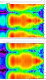
I made some measurements of AmtPro-4 with open back, and add small horn in front of it in form of beams with cross section 20x27 cut under 45 degree towards diaphragm.
11 kHz big bump is EQed out -8 dB, rest is not filtered.
Measurement made with REW and converted to polar plot with VituxCAD.
Did it make sense to use AmtPro-4 as OB tweeter? Plan is to had high pass filter at about 1 kHz.
Did horn in front of it give any advantage or pure AmtPro-4 is better?
Upper plot on image is with horn, lower is pure AmtPro-4 OB.
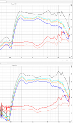
I added also power and DI plots, upper is with horn.
11 kHz big bump is EQed out -8 dB, rest is not filtered.
Measurement made with REW and converted to polar plot with VituxCAD.
Did it make sense to use AmtPro-4 as OB tweeter? Plan is to had high pass filter at about 1 kHz.
Did horn in front of it give any advantage or pure AmtPro-4 is better?
Upper plot on image is with horn, lower is pure AmtPro-4 OB.
I added also power and DI plots, upper is with horn.
Attachments
Last edited:
I have a pair of these and did some measurements (lost to a HDD crash). I recall the distortion started to rise around 1.3kHz and lower. This might limit the low end. You can measure this in your own horn and maybe you have a different result.
The high end rolloff and relatively long length of the diaphragm are not helpful if you want to use this driver all the way up to 20k. If you have a limited hearing range, it might not be a problem for you.
The high end rolloff and relatively long length of the diaphragm are not helpful if you want to use this driver all the way up to 20k. If you have a limited hearing range, it might not be a problem for you.
On my measurements as OB at about 85 dB SPL on 1 m THD start to rise below 900 Hz. Noise level at this measurement is nearly on same level as THD summary.
But how about polar plot with horn and without? Can this be improved with more sophisticated horn form?
Specially DI in range 2-4 kHz?
But how about polar plot with horn and without? Can this be improved with more sophisticated horn form?
Specially DI in range 2-4 kHz?
Attachments

Last edited:
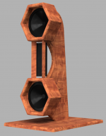
Made my OB nearly ready. It is AmtPro-4 with open back and small horn in front of it in form of beams with cross section 20x27 cut under 45 degree towards diaphragm. Filtered from 1 kHz, LR4, DSP corrected. Mid part is PTT6.5W08-01A in MTM OB configuration with AmtPro-4, not exactly as on image below but nearly, gaps on top and bottom of AtmPro-4 are missing.
Measurement made from 1 m with 4,5 ms gating.
But directivity graph is not as good as was on prototype.
What can cause significant lobbing higher than 3 kHz, why this was nearly missing on prototype?
Measurement made from 1 m with 4,5 ms gating.
But directivity graph is not as good as was on prototype.
What can cause significant lobbing higher than 3 kHz, why this was nearly missing on prototype?
Attachments
Last edited:
Q: What can cause significant lobbing higher than 3 kHz, why this was nearly missing on prototype?
A: The vertical bars are making diffractions in frontal horizontal off-axis response.
How was the proto mounted? Above 2-3kHz a dipole radiator is very very tricky and sensitive to obstructions, causing interferences. This is why many diyers are mounting them with wires.
A: The vertical bars are making diffractions in frontal horizontal off-axis response.
How was the proto mounted? Above 2-3kHz a dipole radiator is very very tricky and sensitive to obstructions, causing interferences. This is why many diyers are mounting them with wires.
Proto was mounted nearly same way only upper mid honeycomb cell was missing,
Horn was on both in form of beams with cross section 20x27 cut under 45 degree towards diaphragm.
Prototype beams where made from pine wood, complete one had oak beams.
Can it help if I made beams outer edge rounding with bigger radius. Oak beams are hard and edges are very sharp, proto pine beams had not so sharp edges, butt difference was in 2 or less millimeters.
Because of construction I need some form of beams to support upper honeycomb cell. Idea was also to make AmtPro-4 radiation to front and back more symmetrical (like H-frame, instead original U-frame), it has on back side big magnets in 2 rows what acts as small horn and in naked installation form U-frame.
Last edited:
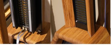
You've got several things going on here. As Juhazi already said, the waveguide-like bevels are reflecting back. The second thing: Your back brace behind the AMT is straight instead curved, it reflects the sound. If it was like in the rendered picture, that would have 'smeared' over a wider range but overall with a lower level.
And: It's a dipole. On your photos the speakers stand right up to the wall. While you may get away with that on a dome tweeter measurement, a dipole radiates to the back too - and the reflected sound interferes with your front side (direct) sound.
And: It's a dipole. On your photos the speakers stand right up to the wall. While you may get away with that on a dome tweeter measurement, a dipole radiates to the back too - and the reflected sound interferes with your front side (direct) sound.
That's a nice / interesting looking build.
"What can cause significant lobbing higher than 3 kHz"
Basically what ICG already said. How to fix it?
Try masking parts of the frame + nearby objects with foam or towels or whatever, and see if that makes a difference. e.g. attach a couple of blocks of foam at the top and bottom of the ATM. If the lobing improves, that would indicate that reflections off the midbass structures are causing the problem.
Another basic thing you can try is masking part of the surface of the diaphragm (just with duct tape or whatever). This will change the pattern of destructive interference that limits the vertical dispersion. It is not perfect, but you can get some improvement this way, and it is very easily reversible + easy to tweak.
That will surely help, good suggestions. As an alternative, you could put the mounting braces on the back of the driver. Or use a plywood as mini-baffle, you could put a veneer on it. If you want to keep the speakers close to the wall (dipoles need distance from the back wall though), you could put a wedge behind the AMT, so it reflects to the side instead of (mainly) the wall. That will improve the resolution and room impression because the 'short' reflections are avoided.
On your photos the speakers stand right up to the wall. While you may get away with that on a dome tweeter measurement, a dipole radiates to the back too - and the reflected sound interferes with your front side (direct) sound.
Reflection from walls is out of question, measurements where made not in same place in room where image was made, also measurement is made with gating, this cuts out reflections.
Other your points need to be considered, but I had missed them partly.
Reflection from walls is out of question, measurements where made not in same place in room where image was made, also measurement is made with gating, this cuts out reflections.
That is if the gate is set correctly. But you are right, at these frequencies that's not likely. It still could be a measurement error or rather a setup error. When measuring the speaker, did you move the speaker (or microphone) with the center point exactly through the plane of the AMT?
^If there was a measurement error, it obviously was with the proto. 3-6kHz interferences are exactly what can be expected with those side "panels/wings" We must remenber that very small changes in dimensions and angles will make an effect at these wavelengths.
Yes, proto and complete version measurements where made in same place, with same equipment and in same way.
^If there was a measurement error, it obviously was with the proto. 3-6kHz interferences are exactly what can be expected with those side "panels/wings" We must remenber that very small changes in dimensions and angles will make an effect at these wavelengths.
Yes, I thought the same, that's why I asked how it was measured.
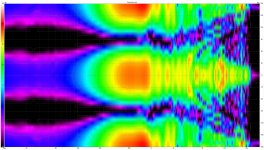
I find one image on other OB measurement/simulation with same pattern, only on little higher frequency:
Full range line array for wall or corner placement
What cause this pattern there?
Full range line array for wall or corner placement
What cause this pattern there?
I find one image on other OB measurement/simulation with same pattern, only on little higher frequency:
Full range line array for wall or corner placement
What cause this pattern there?
That's a line array. The interference is a result of multiple drivers and different distance (=run time) because of the short measurement distance and the "large" (well, for the treble) of the center to center because of the driver size. That becomes a bit better with more distance but will still show and are quite noticeable. That's why there are no really good working LAs with wide band drivers. And placing a tweeter array next to a fullrange array works but then you'll have interferences horizontally and vertically. It's a tough thing to compromise because every improvement on one thing got a drawback elsewhere. Choose your own poison.. 😉
If you have foam pipe insulation in Estonia you could pick up a couple sticks and cover the vertical brace behind the amt with it. The foam is slit along the length and is round. You could also cut a couple lengths of foam and add them to the sides of the wooden waveguide at the front. That alone should even out the response quite a bit. No sharp edges,
Similar polar plot pattern is on middle plot named Dipole TC9.That's a line array. The interference is a result of multiple drivers and different distance (=run time) because of the short measurement distance and the "large" (well, for the treble) of the center to center because of the driver size. That becomes a bit better with more distance but will still show and are quite noticeable. That's why there are no really good working LAs with wide band drivers. And placing a tweeter array next to a fullrange array works but then you'll have interferences horizontally and vertically. It's a tough thing to compromise because every improvement on one thing got a drawback elsewhere. Choose your own poison.. 😉
If I look second image in the post, I understand for dipole simulation there is only 2 speakers what play higher than 700 Hz frequencies and separation between them is 100 mm, what for H-frame mean same as 50+50 mm, little bigger (about two times) than my tweeter had.
Last edited:
Yes, I had different kind of foam insulation available, but this make already not very good looking speakers even more ugly.If you have foam pipe insulation in Estonia you could pick up a couple sticks and cover the vertical brace behind the amt with it. The foam is slit along the length and is round. You could also cut a couple lengths of foam and add them to the sides of the wooden waveguide at the front. That alone should even out the response quite a bit. No sharp edges,
- Home
- Loudspeakers
- Multi-Way
- AMT Pro-4 as OB tweeter