
Thanks, @llwhtt
So I power up with full voltage, and made sure DC offset was good and it is adjustable and stable very close to 0mV (minor drift here and there). But my Bias is not correct, or at least I don't think it is correct. The manual states to measure between the collectors of Q7 & Q9. One manual says set it for 2.2V and the other manual says to set it for 2.0V. My adjustment only allows it to go to 2.5V and both channels act the same. The range is only 2.5 to 2.7V (via the bias pot). These are using the CA3086 and are coupled to the heat sink. I can watch the voltage change a few decimal points as the amp warms up. So it looks like it is tracking.
I want to make sure something is correct or incorrect. Both channels are acting the same. Should I be measuring across R43 / R44? Those are the emitter resistors for the outputs.
Signal on the scope looks good, distortion analyzer readings look good.
I have not powered up the other chimney assembly yet to see how that operates. It also uses CA3086s.
Thanks!
I just rebuilt an Ampzilla I chimney, I used the SAE 2400 method of setting the bias, 1W into 8 Ohm @ 20KHz, adjust for .04%THD. I then measured the collectors and it was 2.3VDC. Ampzilla and the SAE 2400 are VERY close cousins, basically the same circuit.
Thanks. I'll be powering up the other chimney in a day or two. Maybe sooner if my Type A doesn't calm down. I'll report back.
Is it possible the new outputs (MJ15003/4) require bias a bit differently than the early generations of outputs? Without compensating the Bias circuit, it is what it is.
Is it possible the new outputs (MJ15003/4) require bias a bit differently than the early generations of outputs? Without compensating the Bias circuit, it is what it is.
The one I just finished used MJE15034/5 in the top two positions, MJE15028/29 in the bottom two positions, and MJ21195/6 outputs. I used CA3046 or CA3086 for the bias IC. The bias pots were set really low, well less than 100 Ohms for the method I used. I had to remove the 250 Ohm single-turn trimmers and install multi-turn so the adjustment wasn't so sensitive. Does your board have the driver adjustment? Some do some don't. What's the voltage across the 62 Ohm resistors near the upper corners of the board?
Same here, MJE15034/5 & MJE15028/29 with MJ15003/4s in the output (purchased from @jackinnj ). I followed initial Bias setup in the manual of turning the [single turn] pot counter clockwise as you look from the top of the board set down. At that setting the Bias across Q7/Q9 was 2.7V. I'm all the way clockwise and the lowest I can get is 2.5V.
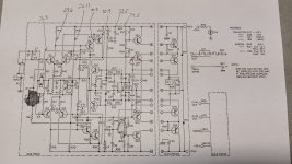
Yes, I'm at 2.6 on each (R21 & R26). I see on the top right of the schematic, it says 1.2 to 1.8.
I do see how the collectors of Q7 / Q9 tie directly to the Bias adjust. So am I looking an issue with the operating point of Q6 / Q7 and Q8 / Q9? I get a bit lost in the details here. I'm curious how the other chimney acts now. All new components are same value as what the manual calls for and I didn't find any thing different when I removed old components.
I do see how the collectors of Q7 / Q9 tie directly to the Bias adjust. So am I looking an issue with the operating point of Q6 / Q7 and Q8 / Q9? I get a bit lost in the details here. I'm curious how the other chimney acts now. All new components are same value as what the manual calls for and I didn't find any thing different when I removed old components.
Yes, both channels pass a signal. Only went to 100 Watts or so thus far. Distortion is low, around .0080%
Well amp #2 behaves perfectly. Bias ranges from 1.6 to 2.6V. The sweet spot seems to be at 2.2 and 2.1 for the other channel.
The only difference between the 2 amplifiers are the differential quad (Q1-4) are original devices on both channels of misbehaving amp. The other amp (correctly behaving) has brand new matched 2N5401s and 2N5551s. Everything else is identical.
The only difference between the 2 amplifiers are the differential quad (Q1-4) are original devices on both channels of misbehaving amp. The other amp (correctly behaving) has brand new matched 2N5401s and 2N5551s. Everything else is identical.
I took one channel of the problem chimney to investigate and repair. I replaced all the original MPSUxx transistors with 2N5401/5551s. That did bring the voltages across R21 and R26 down to 1.9V, but that is on the high side of the range called out on the schematic (1.2 to 1.8V). The voltages at R19, R14 and the collector of Q6 are still a bit high compared to the other channel. Actually about half a volt higher than what I documented here: https://www.diyaudio.com/community/...33fc66d4c7684cca99c41e8eb.jpg?hash=h62rBUns9u
DC balance is great. Adjustment of R5 is in the middle of the pot range and no drift.
Bias is messed up and has been. The instructions say to turn the pot counter clockwise as you look down the boards from the top. 'This is is the lowest resistance of the potentiometer'. That is correct and measures thus with a meter when checking it. Powering it up, Bias is at 2.8V (as measured between Q7/Q9 collectors) at the 'lowest Bias setting' and then drops to 2.4 as you turn the pot clockwise. This is BACKWARDS. The Bias voltage should be around 1.4V at that pot position and increase as you turn clockwise. I pulled the CA3086 and checked the transistors in the DIP and they are fine. I even Ohm'd the legs to the solder side to make sure everything was making contact within the [white] socket.
The working amp is working just fine. Bias voltages are in range and increment properly with clockwise rotation of the potentiometer. Both units have the same board. I compared components visually and even took some resistance measurements at various points to compare. Nothing is jumping out at me.
The only active devices not changed on these boards is the Zener and regular diodes. They were checked upon servicing.
Try reducing R23/24, what do you have that's a bit lower than 150K? The SAE 2400 used 270K for R23/24 and then has a 100K resistor and a 100K trimmer. Do you have the empty locations for another resistor and trimmer?
Last edited:
My boards have provisions for R74 (potentiometer) and R75 (resistor), but they are not installed [and this applies to the boards that act properly and the boards that do not act properly].
I put a resistor in parallel with R23/24 to drop them to 100K and it didn't do much to change Q7/Q9. This was BEFORE I replaced the MPSUxx transistors. I'll try again.
I still don't understand the Bias being backwards. Unless it is because there is an imbalance between the base of Q13 / 14 where the Bias is located. On the good amp, the voltages are 1.12 and -1.12 (at the base of each w/ respect to GND). On this problem amp, it measures 1.32 & -1.12.
I know I matched the MJE15034 /35s to each other and the MJE15028 / 29s to each other. I didn't just throw random devices in.
Ok, made progress finally.
Problem 1: MPSUxx transistors in the front end doing weird things with quiescent current through Q7/Q9. Replaced with all new matched 5551/5401 devices.
Problem 2: Zener Diode removed from circuit and inspected. It was a 45V zener. Throwing front end voltages off after new Transistors installed. I already had new 51V Zeners ready to go.
Problem 3: Current throught Q7/Q9 was still a bit high and voltage across the 62 Ohm resistors was 1.8V. On the high side. I did look at the 2400 schematic to see how they implemented. I just changed the R23/24 150K resistors to 120K and that dropped the voltage to 1.6V. This also brought the Bias voltage down going into the Bias circuit.
Assembled and adjusted Bias per the SAE method. Sweet spot found and voltage across Q7/Q9 is 2.4V.
Thanks for help along the way.
I have been matching my MJE devices as best as possible. Any other recommendations...please share.
- Home
- Amplifiers
- Solid State
- Ampzilla Outputs Using MJ15022