Hey guys.... first of all thanks to the OP and contributing members! My first sim and need your help its an old amplifier and the sim does not cover its transistors what to do?
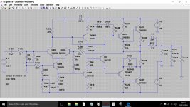
Here is the amp..
Here is the amp..
Attachments
Last edited by a moderator:
here is my attempt to my first sim sketch
need little help does anyone see errors ...it did run well kinda but now when added power supply comes up with Q7 error but it still does run
Thanks for your help
Lawrence
need little help does anyone see errors ...it did run well kinda but now when added power supply comes up with Q7 error but it still does run
Thanks for your help
Lawrence
Attachments
Last edited:
Here's what I would do...
use Bob Cordells excellent models and initially set the sim up use common parts. Actually, you could use the default LT models. Try 2N5550 for the small signal NPN's and 2N5401's for the small signal PNP's. Use 2N3055's for the outputs.
That will get you a working sim. Use1N4148's for all the small diodes and MUR320 for the Baxandall diode.
Then you can have a play with different models 🙂
Hadn't turned the page and seen your last post. Ooops 🙂
I'll take a look at your file a little later. Feeding time.
I'll take a look at your file a little later. Feeding time.
Thanks
Thank you sir...I will give it a go ...but the whole purpose was to model the amp and do some playing around with pos feedback ah la nelson passes newly reinvented idea
will there be a way to implement these old parts in the sim?
going for a bike ride now still beautiful out here in northern texas!
I will input the numbers when i return and play around
Thank you so much!!
Lawrence
Cold and wet here (lol, just for a change)
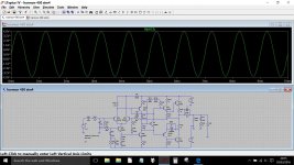
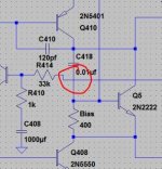
Try this revised sim for starters... and yours was a great effort 🙂 You need to watch your units, for example a cap of 220 would actually be 220 Farads. Make sure you enter uf or pf etc. C418 was set at 0.01 (Farads).
Leaving transistors with no type number just defaults to a generic set of values which never seem to work well for things like this.
We don't need add rail decoupling at this stage because the rails are 'perfect' and with zero impedance which means noise and ripple is non existent... but you can change that 😉
Delivering 1 watt into 8 ohms. I've set the bias at around 55 ma.
I'll look in again tomorrow.
Try this revised sim for starters... and yours was a great effort 🙂 You need to watch your units, for example a cap of 220 would actually be 220 Farads. Make sure you enter uf or pf etc. C418 was set at 0.01 (Farads).
Leaving transistors with no type number just defaults to a generic set of values which never seem to work well for things like this.
We don't need add rail decoupling at this stage because the rails are 'perfect' and with zero impedance which means noise and ripple is non existent... but you can change that 😉

Delivering 1 watt into 8 ohms. I've set the bias at around 55 ma.

I'll look in again tomorrow.
Attachments
Your modification (R2=105K) doesn't feed back signal. It does change the tail current of the input differential pair from 1 mA to 19 mA. That puts a lot more gain in the first stage. The increase in the loop gain is responsible for the lowered distortion, though I'd say 19 mA of tail current is kind of too high.
A couple of things struck me as odd in the original circuit, notably the area around Q406 and its bias network. The values given actually work OK in simulation, or at least with the models I used but it all appears to be on a knife edge to me. Q406 at first glance looks as though it is a CCS in the tail of the LTP... but it isn't. Its a transistor running starved of base current where the hfe of the device will have significant impact on the operating conditions.
Q
Hi Mooly this is/was a commercial receiver amplifier the Harmon Kardon 430
my favorite amplifier 😀 I have been experimenting looping voltage back to the input of the amplifier like in the article about pos feedback....This does not seem to work in this amplifier....any reason why it would not ?
where i looped some voltage around Q406 seemed to give a significance reduction in distortion but I am afraid that it works in the sim but reality maybe different!?
Lawrence
Last edited:
The point you are applying feedback to looks wrong tbh. D402 and C405 simply clamp any positive voltage excursions to the negative rail... well a bit more to it than that but you get the idea.
If you make the base of Q406 more positive then it has the effect of bringing the output more negative. So applying signal from the output back to that node is really adding more negative feedback which could well be why you see a reduction in distortion.
If you make the base of Q406 more positive then it has the effect of bringing the output more negative. So applying signal from the output back to that node is really adding more negative feedback which could well be why you see a reduction in distortion.
The point you are applying feedback to looks wrong tbh. D402 and C405 simply clamp any positive voltage excursions to the negative rail... well a bit more to it than that but you get the idea.
If you make the base of Q406 more positive then it has the effect of bringing the output more negative. So applying signal from the output back to that node is really adding more negative feedback which could well be why you see a reduction in distortion.
no I have also looped it back to the base of the q402 also put in front of the 47uf input cap does not seem to help ...
I am asking for your help and understanding
Lawrence
no I have also looped it back to the base of the q402 also put in front of the 47uf input cap does not seem to help ...
I am asking for your help and understanding
Lawrence
You need to be extremely careful when introducing positive feedback not least because of the result of destructive oscillation. You will probably also find that the DC conditions shift substantially.
This shows a small amount of positive feedback together with R408 having been made variable to tweak the offset to zero vaults.
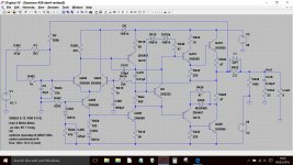
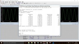
And here is the distortion spectrum. Not pretty 🙂

Attachments
little better
As per the paper i read, the resistor multiplier should be 9 times what the neg feedback resistor is (33k) so 2.6meg in the pos feedback producted lower distortion but terrible looking fft
the Goal is to lower the total harmonic distortion without changing or lowering neg feedback
As per the paper i read, the resistor multiplier should be 9 times what the neg feedback resistor is (33k) so 2.6meg in the pos feedback producted lower distortion but terrible looking fft
the Goal is to lower the total harmonic distortion without changing or lowering neg feedback
Attachments
Last edited:
It took me a moment or two to spot it, but in the sim above you have altered the line connecting the main feedback to R414 and in so doing tagged it to the base of Q5. If you look at my version you'll see I dropped that line down a fraction to avoid that.
Chasing lower and lower distortion for a given design doesn't always improve the perceived sound quality.

Chasing lower and lower distortion for a given design doesn't always improve the perceived sound quality.


Oops I didn't realize that when you cross cross lines that they now connect?!
Anyways I totally agree if amplifiers were designed only by specifications well no need to reinvent because they have been (spec) wise perfect lol
I use this amplifier for music not my bench instruments but I am curious as to such a good sounding amplifier with less distortion would be like
Lawrence
Oops I didn't realize that when you cross cross lines that they now connect?!
It happens when lines cross what would be the 'terminal' of the other part.
Ultimately the only way to investigate sound quality and properties of different designs and variations on designs is to actually build them. Simulation tells you a lot but it can't be the final decider in sound quality.
Ultimately the only way to investigate sound quality and properties of different designs and variations on designs is to actually build them. Simulation tells you a lot but it can't be the final decider in sound quality.
Where simulation comes in is when you find out what sounds good, but you want to investigate and see if you can determine why. You can simulate to find out what changed, and then you can see if you can improve it further.
That said, there is nothing wrong with learning from the simulator, as long as you investigate the results to see if they make sense in real life, and if not find out WHY.
- Status
- Not open for further replies.
- Home
- Amplifiers
- Solid State
- Amplifiers for the musical truth.
