Try with a lower amplitude. Aim for something like 10 Vpp at the output. Set the frequency to 10 kHz.
Tom
Tom
R6 R11 are too big. Replace them with 1K 1K.
Why are there 4 diodes? I believe it should be 3.
Why are there 4 diodes? I believe it should be 3.

R6 R11 are too big. Replace them with 1K 1K.
Why are there 4 diodes? I believe it should be 3.
works fine but the bias is too high with 1k 1k
As connected, R16 does nothing useful. Should Q6 emitter be tied to Q8 collector? (A few ohms in series with Q6 emitter might help Q8,Q6 local stability.) Or should R16 be deleted? I have no firm opinion.
No, R16 should simply be moved to the emitter. It is then the most symmetrical arrangement possible, with the exception of doing that and then adding a Baxandall diode in series with Q6 emitter. A CFP with Q6 emitter tied to Q8 collector, then both run thru the resistor is the “right” way to do a CFP, but it is less symmetrical than the other proposal. Do them that way if they are complementary, of course.
Yep, that should be done also.Should Q6 emitter be tied to Q8 collector?
i will do that too but could i replace the op amp with something like the lm393?No, R16 should simply be moved to the emitter. It is then the most symmetrical arrangement possible, with the exception of doing that and then adding a Baxandall diode in series with Q6 emitter. A CFP with Q6 emitter tied to Q8 collector, then both run thru the resistor is the “right” way to do a CFP, but it is less symmetrical than the other proposal. Do them that way if they are complementary, of course.
Guess you could add an external bootstrapped collector load, but no way to miller compensate. Which is normally internal to the op amp. You’d have to try basic lag compensation.
Like that, Drive the diode string center, with Bootstraps which gets max swing from opamp. P1 adjust bias
Dont change the currents with wild guessing. Using modern 2n3055 models.

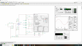
Square wave 20 kHz 8 ohm No ripple, dam good slew for 3055. More than stable

Gain 25dB 2 Hz to 1.6 MHz

10watts 8 ohm
1kHz .006% distortion
10watts 4 ohm
1kHz .006% distortion
Max Clean Power 4 ohm 15.76 Watts
1kHz .007% Distortion
20 kHz .06% Distortion


10 kHz 5volt P 10volt PP 90% and 10% 4 volt
.287 us 8 volts 27 V/us Slew rate


Dont change the currents with wild guessing. Using modern 2n3055 models.
Square wave 20 kHz 8 ohm No ripple, dam good slew for 3055. More than stable
Gain 25dB 2 Hz to 1.6 MHz
10watts 8 ohm
1kHz .006% distortion
10watts 4 ohm
1kHz .006% distortion
Max Clean Power 4 ohm 15.76 Watts
1kHz .007% Distortion
20 kHz .06% Distortion
10 kHz 5volt P 10volt PP 90% and 10% 4 volt
.287 us 8 volts 27 V/us Slew rate
Attachments
what if i switched to an complementary transistor pair? i also have 4 "matched" trtansistors from an power supply
Complementary pair is Way The Hell Better. The PNP side won’t do annoying unexpected unpredictable things like oscillate. Someone playing with 2N3055’s might not have modern ones.
And then you will always get the emitter resistor in the right place.
Also, my experience is that 2N3055’s, even modern ones can demand more than 200 mA of base current. 2N2222/MPS2907 solve that little problem nicely.
And then you will always get the emitter resistor in the right place.
Also, my experience is that 2N3055’s, even modern ones can demand more than 200 mA of base current. 2N2222/MPS2907 solve that little problem nicely.
2.2R is a very low value for a Zobel network / Becherott cell load - usually ~10 ohms is used. Have you tried such a value?it works it seems that the bucherott cell/zobel network creates these socilations
The normal reason for instability is a lack of phase margin due to too many RC stages in series within the global loop (each active device can provide the equivalent of an RC stage), and a simple if crude fix is to provide a bit more feedback from the opamp output direct to its inverting input via a small capacitor, i.e. a "Cdom". The downside to this is the feedback loop becomes less effective at linearizing due to the greater fall off of open-loop gain at higher frequencies.
Another approach is use faster transistors (or FETs) so that the phase delays are smaller in the loop.
- Home
- Amplifiers
- Solid State
- amplifier oscilates in LTspice