D
Deleted member 148505
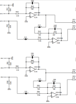
I actually cannot find decent IRFB4227 class-d modules on aliexpress (at least with my standard), so I designed one myself.
Gain should be around 29dB. (2Vrms in, 56Vrms out at 4Ω/8Ω). Target >= 80dB SINAD at 5W 4Ω. Max voltage +/-85V.
Used switching regulators for housekeeping supplies to avoid excess heat. Onboard low noise opamp buffer since I've added PFFB components for experimentation. Price will be around 80USD.

Gain should be around 29dB. (2Vrms in, 56Vrms out at 4Ω/8Ω). Target >= 80dB SINAD at 5W 4Ω. Max voltage +/-85V.
Used switching regulators for housekeeping supplies to avoid excess heat. Onboard low noise opamp buffer since I've added PFFB components for experimentation. Price will be around 80USD.
Last edited by a moderator:
Hi,
Here is my assembly with x3 D100 modules.
https://www.homecinema-fr.com/forum...ymetrique-faible-bruit-termine-t30127894.html

How to reduce the gain by 6dB?
Here is my assembly with x3 D100 modules.
https://www.homecinema-fr.com/forum...ymetrique-faible-bruit-termine-t30127894.html
How to reduce the gain by 6dB?

Presently for Sylph-D100, the buffer's gain can be reduced by changing 4pc 0805 resistors. (input stage currently at 3x, multiplied by PFFB gain at 1.367x for a total voltage gain of 4.1x)
What value of resitors for an unity gain input stage ?
If Bypass, how to do it and what input impedance value?
Last edited:
What a gorgeous buidl! Can you share some more about the internals and parts used beyond the D100's?Hi,
Here is my assembly with x3 D100 modules.
https://www.homecinema-fr.com/forum...ymetrique-faible-bruit-termine-t30127894.html
View attachment 1224066
How to reduce the gain by 6dB?
D
Deleted member 148505
Change the resistors from 3.3K to 10K 0805 for unity gain input stage.What value of resitors for an unity gain input stage ?
Feedback resistors and caps are under the opamp socket so they are difficult to replace. (You can change to 4.7K input resistor and 4.7K || 680p feedback without stability problems. But the current config is the most compatible with different opamps for a socketed configuration, especially if you use the boutique / discrete opamps)
It's easier to replace the opamp socket if you destroy / split the socket in 4pcs using side cutting pliers and desolder each section (2pins) simultaneously.
I suggest not to do a bypass, because at this level of performance, an onboard buffer is required, wiring the buffer outside the feedback loop may actually worsen the SINAD due to long wiring.If Bypass, how to do it and what input impedance value?
Attachments
D
Deleted member 148505
Changing r_in (RP1...RP4) to 6.99K will make the performance of PFFB to 105dB to 106dB SINAD at 1kHz 5W 4R.
Although you have to increase the opamp supply as well (requires changing another 4pcs 0603 SMT on the supply section)
But... the present 5.1K values do sound the same. (6.99K r_in = 106dB SINAD vs 5.1K r_in = 103dB SINAD, just 3dB difference)
So, you might understand my design decisions here for this module... It's a balancing tradeoffs act.
****
Deepening the PFFB is just changing the ratio of r_fb and r_in, maintaining stability is the challenge.
Last edited by a moderator:
Thanks. At the transformer primary, a dc blocker and on secondary, a pi filter. 47000µF, 6.8mH inductor (Rdc 0.16 Ohms) and 47000µF.What a gorgeous buidl! Can you share some more about the internals and parts used beyond the D100's?
Thanks for all the answers.I suggest not to do a bypass, because at this level of performance, an onboard buffer is required, wiring the buffer outside the feedback loop may actually worsen the SINAD due to long wiring.
I was thinking of possibly directly attacking the power stage with PFFB. I use a motu 24ao symmetrical sound card which already has its own output AOP compatible with a 1kOhm load.
I did this on a basic tpa3255 based amp (but without PFFB).
You think it's better to keep the buffer ?
D
Deleted member 148505
This would work in a non-PFFB board. In a PFFB setup, the moment you disconnect the MOTU, the module will go into protection mode.I was thinking of possibly directly attacking the power stage with PFFB. I use a motu 24ao symmetrical sound card which already has its own output AOP compatible with a 1kOhm load.
There are onboard jumpers under the PCB to disable the PFFB. Some D100 users prefer the D100 with the PFFB disabled.
If you have followed this thread, I've created a gain buffer module for this purpose.You think it's better to keep the buffer ?
Although the last time I tried it is that the r_in is on the gain buffer module, hence the long wiring affected the SINAD performance.
I will try again with the r_in located on the Sylph-D100 board. Though it will surely lose 1dB or more SINAD if the opamp buffer is away on the PFFB network. So still the recommendation is to retain the onboard buffer.
Ok, thanks.
In my use, I don't need any additional external gain, I don't use all the power of the amp.
So, I'm going to modify the gain with two 4.7 kOhm resistors (unity gain buffer).
Without PFFB, the output noise is to high.
In my use, I don't need any additional external gain, I don't use all the power of the amp.
So, I'm going to modify the gain with two 4.7 kOhm resistors (unity gain buffer).
Without PFFB, the output noise is to high.
D
Deleted member 148505
If the opamp section is unity gain, the total gain of D100 will only be 2.6dB (1.35x voltage ratio). So, you need a preamp that is capable of outputting 15Vrms to drive the amp into clipping.I don't need any additional external gain
Nice, with 4.7kOhm resistors I think the buffer won't be a performance bottleneck especially if you use OPA1656.So, I'm going to modify the gain with two 4.7 kOhm resistors (unity gain buffer).
D
Deleted member 148505
Hi,
Here is my assembly with x3 D100 modules.
https://www.homecinema-fr.com/forum...ymetrique-faible-bruit-termine-t30127894.html
How to reduce the gain by 6dB?
Speechless on your build quality.
Regarding DC offset that you've encountered, the polarity of the capacitors has been overlooked on assembly. On non-PFFB mode, the input coupling cap's negative side is on the opamp output (ground referenced due to opamp split supply then the TPA325x input is referenced to AVDD/2).
On PFFB mode, the polarity changes (feedback referenced to PVDD/2 on each out_x).
So the default input coupling cap's polarity assembly should have been on default PFFB mode, we will do it going forward.
Last edited by a moderator:
Finally, i replaced the 3.3k by 6.8k to keep a little more gain and facilitate the return to origin.
OPAMP replaced by LME49720.
I had made this reasoning for the positioning of the capacitors based on the presence or absence of PFFB.
OPAMP replaced by LME49720.
I had made this reasoning for the positioning of the capacitors based on the presence or absence of PFFB.
D
Deleted member 148505
What's the DC supply voltage of your setup?
You can also try OPA1612, it will get similar voicing as PA5.OPAMP replaced by LME49720.
Transformer 2x12Vac in series for a measured DC voltage of 37.5V.
I am thinking of replacing the transformer with a 1x19Vac.
I am thinking of replacing the transformer with a 1x19Vac.
D
Deleted member 148505
You need a mains voltage regulator (AVR) since your supply is unregulated. Although there is a TVS diode onboard for transients.Transformer 2x12Vac in series for a measured DC voltage of 37.5V.
D
Deleted member 148505
HV DC-DC converter got out of stock. 🤦♂️I actually cannot find decent IRFB4227 class-d modules on aliexpress (at least with my standard), so I designed one myself.
Gain should be around 29dB. (2Vrms in, 56Vrms out at 4Ω/8Ω). Target >= 80dB SINAD at 5W 4Ω. Max voltage +/-85V.
Used switching regulators for housekeeping supplies to avoid excess heat. Onboard low noise opamp buffer since I've added PFFB components for experimentation. Price will be around 80USD.
View attachment 1223032
Replacing with LM5164 converter IC.
Used 2W isolated DC-DC 12V to +/-12V for the analog supplies.
800W Peak into 4 ohms
D
Deleted member 148505
SylphAudio Preamp has taken its shape. 🙂

- No input coupling caps on the signal path.
- 5x OPA1612, 10dB gain, can be reduced by 10K volume potentiometer.
- Relay switching for SE/Diff input selection.
- Simultaneous SE and Diff output (had to look at my DO100 DAC on how it's being implemented lol).
- 11.5Vrms max for SE, 23Vrms for Diff output
- Single 24V to 60V DC supply input.
- Expected THD+N: -120dB at 1kHz, 0dB gain.
D
Deleted member 148505
0dB gain is the default. I added empty 0805 SMT pads (circled in yellow) so that the gain can be easily increased.10dB gain, can be reduced by 10K volume potentiometer.
Frontend buffers are non-inverting for high impedance input.
FR flat at 20Hz to 20kHz, -3dB is at 96kHz,
Will test the prototype in a couple of weeks (Victor's osc + Cosmos APU + MOTU UL MK5 ADC)
Would be really interested to see if this enables ultra-low SINAD for future TPA325x amps where PFFB is maxed to the limit.
- Status
- Not open for further replies.
- Home
- Vendor's Bazaar
- Amplifier Modules and PCBs For Sale