Commstech, please can you compare sound of LT1364 and LME49860 in this amp?
Pete, looking into 3255 datasheet (or into slaa788), I can't find the recommendations for output cap. Do we need cap that will withstand given AC voltage at switching frequency (600kHz) or at filter frequency (45kHz) ? This is important question as most caps will greatly derate with rising frequency...
Pete, looking into 3255 datasheet (or into slaa788), I can't find the recommendations for output cap. Do we need cap that will withstand given AC voltage at switching frequency (600kHz) or at filter frequency (45kHz) ? This is important question as most caps will greatly derate with rising frequency...
Very good reading, thank you! We already have 24th here, so this "book" counts as my first Christmas present 😀
Although my question about frequency upon that output cap is not directly answered there, based on page 8 it seems that requirements for that cap are quite high...
Although my question about frequency upon that output cap is not directly answered there, based on page 8 it seems that requirements for that cap are quite high...
ppppp, glad I got you something nice for Xmas this year..😉
I’m just trying to learn stuff as I go, just like you and a lot of other folk in these DIY forums.
FYI, the 3e 3255 amp board, 1st version of TPA3255-2CH-260W amp used 10uH inductors and a 1uF cap for the LC filter. The second version of his TPA3255-2CH-260W, the one with replaceable op-amps, used 10uH inductors but .68uF caps on the LC filter and the 2nd version sounded a lot nicer than version #1. I was hoping to try that variation on Lester’s amp but then I remembered Lester’s board is PFFB while the 3e board I does not have PFFB implemented so there’s more leeway in changing some components.
But, there’s always some component to diddle with...hahahahaha
Merry Christmas,
Pete
D
Deleted member 148505
D
Deleted member 148505
The output cap that was used in 3eAudio module is small. Looks like it is running at its limits already affecting the heating and/or filter capability maybe that's why they replaced it with 0.68uF. Or maybe 1uF value for that footprint with appropriate voltage rating is rare . For metallized film I think 250V AC rating has plenty of margin.ppppp, glad I got you something nice for Xmas this year..😉 I'm just trying to learn stuff as I go, just like you and a lot of other folk in these DIY forums. FYI, the 3e 3255 amp board, 1st version of TPA3255-2CH-260W amp used 10uH inductors and a 1uF cap for the LC filter. The second version of his TPA3255-2CH-260W, the one with replaceable op-amps, used 10uH inductors but .68uF caps on the LC filter and the 2nd version sounded a lot nicer than version #1. I was hoping to try that variation on Lester's amp but then I remembered Lester's board is PFFB while the 3e board I does not have PFFB implemented so there's more leeway in changing some components. But, there's always some component to diddle with...hahahahaha Merry Christmas, Pete
@ppppp we need cap to withstand filter corner frequency. There is TI note slaa701a minimum 250V for tpa325x
Capacitors
Hello
Happy Christmas to all
Bruno Putzey talks briefly about these capacitors
Switching Amplifier (Class D) Basics - page 2 | Audioholics
Best regards
Roger
Hello
Happy Christmas to all
Bruno Putzey talks briefly about these capacitors
Switching Amplifier (Class D) Basics - page 2 | Audioholics
Best regards
Roger
The output cap that was used in 3eAudio module is small. Looks like it is running at its limits already affecting the heating and/or filter capability maybe that's why they replaced it with 0.68uF. Or maybe 1uF value for that footprint with appropriate voltage rating is rare . For metallized film I think 250V AC rating has plenty of margin.
He certainly didn’t intend MKPs to be used on the board. They’re all rated at about 100V. I’m only driving his board with a 36V PS and I don’t crank the dB levels in the room so they’ll probably do for my applications. To drive inefficient or low ohm speakers, or driving a home theater sub-woofer (especially using 48-51V PS) they may be tested, certainly.
Pete
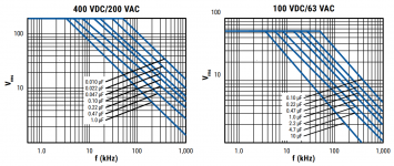
Guys, I wish your statements were true, but I'm affraid it is not that easy. Looking into datasheets of most caps (at least foil types), the voltage is derating at higher frequencies. The higher the frequency, the less voltage it can withstand.
As example, KEMET SMR 1uF:
On the board there is room for 15mm lead spacing, so 63 VAC 1uF cap. Now look at chart. At 45kHz it derates from 63Vrms to only 24Vrms. And as a rule of thumb the capacitor's voltage should be twice of the voltage used in circuit. So in reality, with 1uF 15mm KEMET SMR, we are limited to safely use only some 12V continuous output, or some 1/4 of amp's designated power.
Strange thing is, that the biggest SMR cap with 27.5mm lead spacing rated at 200 VAC, derates even more. At 45kHz it can withstand only 20Vrms. 200VAC cap!
Attachments
D
Deleted member 148505
Guys, I wish your statements were true, but I'm affraid it is not that easy. Looking into datasheets of most caps (at least foil types), the voltage is derating at higher frequencies. The higher the frequency, the less voltage it can withstand.
As example, KEMET SMR 1uF:
On the board there is room for 15mm lead spacing, so 63 VAC 1uF cap. Now look at chart. At 45kHz it derates from 63Vrms to only 24Vrms. And as a rule of thumb the capacitor's voltage should be twice of the voltage used in circuit. So in reality, with 1uF 15mm KEMET SMR, we are limited to safely use only some 12V continuous output, or some 1/4 of amp's designated power.
Strange thing is, that the biggest SMR cap with 27.5mm lead spacing rated at 200 VAC, derates even more. At 45kHz it can withstand only 20Vrms. 200VAC cap!
The graph is for 100 deg C ambient + 20 deg C self heating so I think it is for extreme conditions already.
TI note slaa701a has lots of info for cap derating
Last edited by a moderator:
Yes, at ambient temp. it will be better by couple of %.
In slaa701a, there is not much usefull infos about this particular concern, other than the fact that they selected charts that are worse than the SMR cap, so the SMR is actually the best (most durable) small film cap I have found so far (looking also at derating of WIMAs etc). So it is sort of pleasing result 🙂 And, in the end, I will be using the amp in similar conditions as Pete - with 36V supply and not playing at disco volumes. That said, maybe my worries are not relevant and will allow to use/test different caps without problem... I hope.
In slaa701a, there is not much usefull infos about this particular concern, other than the fact that they selected charts that are worse than the SMR cap, so the SMR is actually the best (most durable) small film cap I have found so far (looking also at derating of WIMAs etc). So it is sort of pleasing result 🙂 And, in the end, I will be using the amp in similar conditions as Pete - with 36V supply and not playing at disco volumes. That said, maybe my worries are not relevant and will allow to use/test different caps without problem... I hope.
D
Deleted member 148505
There is 450kHz ripple voltage after the inductor, which will be filtered by the output cap. The ripple current will make the capacitor heat up at idle.
Then there is DC peak to peak voltage + some overshoot which I think is nothing to worry about.
Then there is audio output, 20kHz worst case.
There is also ripple voltage at the clipping point which is 1/4 switching frequency for TPA325X (112kHz).
Worst is if the amp amplifies the peak at the corner frequency at open load (unstable event).
PFFB circuit is less stable to clipping than non-PFFB.
I'll check if I can tie the !CLIP_OTW pin to !RESET pin so the amp will be muted at the onset of clipping. I measured onset of clipping for TPA3255, around (48VDC - 6VDC) * .707 = 29.7Vrms.
For 36V DC, onset of clipping is around 21.21Vrms. The CLIP_OTW LED will start to light at that output
Wow Pete, thanks for coming back with these findings. I am currently happy with the sound, having only experimented with the op amp NE5532, LME49720, LT1364 and LME49860. My liking is more towards LME49860 now but i intend to order OPA1656 and some other op amp to try out. i shall be experimenting with the pre opamp caps and the pre Tp3255 Caps soon for different flavours.
The 49860 is a fine sounding op-amp. The choice between it and 1656 is a personal one. As usually stated by the more engineering oriented, any of the above op-amps will sound good if the design is built around it. Unlike the acceptable & fashionable audiophile-oriented practice of tube-rolling (where distortion is beautiful?) the practice of op-amp rolling, searching for a holy grail of sound, is fraught with troubles many of us choose not to test for (or can’t properly test for) but hope we don’t hear. But it’s ignorantly fun, no?
Merry Christmas,
Pete
D
Deleted member 148505
I'd take this statement back.PFFB circuit is less stable to clipping than non-PFFB.
For TICore260BTL, PFFB is stable even to clipping at open loads (tested at 1kHz square wave). I will release test results for different frequencies after a month.
So tying up !CLIP_OTW and !RESET is not necessary.
Regards,
Lester
D
Deleted member 148505
Hello
The results are very good, it may be necessary to improve the wiring, shielding, partitioning, mains filter etc.
The heating of the AOP of the interface may be due to the absence of a 200kHz filter used during AP class D measurements.
Roger
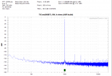
I modified the interface, I placed additional feedback cap on opamps to reduce bandwidth, and changed some resistors, the opamp has less heat now. I will optimize it further. Next month I will use low noise post switching LDO.
Here's the result of my ASR build with the interface running for 10mins (0.0011%).
Noise is slightly higher, it will be improved once I use ultra low noise LDO.
Best is 0.0008% THD, I have to optimize the interface further to get consistency.
Attachments
I will try 10uF Panasonic FR for pre-3255 position based on this guy's review. Looks compatible with TPA3255's sound signature which is warm
Miniature electrolytic capacitors shootout - Best for Coupling to Headphones?
Lester: Did you ever get around to trying the Panasonic FR caps?
Pete
D
Deleted member 148505
Lester: Did you ever get around to trying the Panasonic FR caps?
Pete
Yes, bass and treble is good but I think the clarity is not 'Hi-Fi' enough.
I will try 22uF Silmic II, might be better than 10uF.
- Status
- Not open for further replies.
- Home
- Vendor's Bazaar
- Amplifier Modules and PCBs For Sale