I only buy soup can caps surplus, period. They just want too much for them otherwise. Buy a couple when you find em, see if they form correctly, then get more. Form them when you get them, keep a stockpile, and store them inside in the AC after a complete discharge. Properly stored, shelf life is long. Can’t say as much for the typical little 10 uf leaded electros. Those do go bad rather quickly.
What do you mean by "soup can"?
Stuff from surplus outfits like the skycraft in orlando?
I searched Digikey and Mouser. The prices for 2N3055 are $5-$6 each. That is 2X the price of a good power MOSFET. Is there a cheap source of good 2N3055? Jameco has some cheap 2N3055 but I am not sure of the quality.
I saw them on the onsemi site at barely $3 a pop. Still available.
I guess pricing can vary quite a bit, but they definitely have been rising sharply in the recent past.
Identifying a good source, not too expensive and not fakes, is a must. We need this.
Actually if the 3055/2955 get too hard to get, at decent price and not fakes, we could fall back on their MJ15015/16 versions, which are still basically 3055s, sort of. They are also rather pricy, but they may remain available longer than the 3055s.
I suppose no change would be needed to the design made for 3055s, the MJs should be drop-in compatible.
I suppose no change would be needed to the design made for 3055s, the MJs should be drop-in compatible.
S/B point is at 40 volts, same as 3055. And typical beta is 15 at 15 amps vs. only 7 for the 3055.
And what about other specs? mostly the same?
If I end up building one of these grounded bridges, you know what I’ll be using for outputs. The other application I had in mind was rail modulators for a nice 100 watt class H i prototyped a few years back.
That'll be interesting.
I'm not a fan of the class H myself, not any more than the mosfet amps.
If you test those TO3s for s/b, it'd be nice to know what they can do.
The end result might be surprisingly better than the old 3055 designs that have been done and tested for years. I hope.
The newer faster devices should at least make some difference in bandwidth and transient performance. The amp might render a clear high end better than older designs with the old parts..
Mouser has TIP3055 and TIP2955. These appear to be a TO247 variant of the 2N3055. Anyone have experience with these?
What do you mean by "soup can"?
Stuff from surplus outfits like the skycraft in orlando?
Soup can = large can computer grade cap with screw terminals.
Skycraft - bingo. And other places like it. I’ve bought a lot of soup cans from them over the years. Last Christmas I got a couple of 1000 uF 450 volt soup cans. For building a 250 watt tube bass guitar amp....
There are a couple local places in the Dallas area. Not as big as Skycraft, but I can get to them more than once a year.
Mouser has TIP3055 and TIP2955. These appear to be a TO247 variant of the 2N3055. Anyone have experience with these?
Been there built that bought the T shirt. But mine were in the old TO-218 case. They used to offer both, and the 218s (from ST) show up surplus for a buck or less all the time.
Been there built that bought the T shirt. But mine were in the old TO-218 case. They used to offer both, and the 218s (from ST) show up surplus for a buck or less all the time.
Any performance advantage or disadvantage of the plastic TO247 vs the aluminum can version?
Max TJ is lower on plastic packages, so average power dissipation capability is lower. Current gain isn’t any worse - or better.
They used the TIP3055s in a lot of older car amps, where the supplies were in the +/-25 range, driving 2 ohms. The plastic packages were a lot easier to shoe horn into those amps than the TO3s were.
They used the TIP3055s in a lot of older car amps, where the supplies were in the +/-25 range, driving 2 ohms. The plastic packages were a lot easier to shoe horn into those amps than the TO3s were.
Besides their lower power dissipation capabilities and lower TJ, the TIP parts are identical, so it would work about the same, except that to be safe, more pairs could be used.
Of course the pcb layout and heatsinking would differ, but the main design would remain largely the same.
I suppose at some point when we get a proper protection scheme working on this design, we can explore the 5 pairs version, which I have simulated and it works great as well.
I didn't think of the 5 pairs version as being used with the TIP parts, but rather for possible bridging of the bridge, because in that case each bridge would see a 4ohms load, which means 2ohms per side, so 5 pairs is a good idea in that case.
But I guess there is no reason not to be able to use the TIP parts, and with the 5 pairs version, it should be just fine.
In any case, with proper protection and maybe a thermal sensor on the sinks, this design should be robust, even with the lower powered TIP parts.
When time comes to lay out a pcb, someone could work on a version for the TIP as well.
The heatsinks could be the simpler ones with a flat back surface to mount everything on a single sink.
I've been trying out many possibilities for protections, including my latest, which was acting on the current source at the diff input to pull the rug from under it, but this didn't pan out either.
Perhaps there might be a way to devise something similar to what crown is using in their own amps, which sense for SOA in a quite different way and act in a totally different way as well. Their amps are very robust, so maybe there is something there to do.
Also I'm experimenting on adding a limiter at the input, to prevent hard clipping. The VI protections are mostly to protect the amp, while a clipping prevention is to protect the speakers from the amp.
I looked again into the crown ODEP scheme for protections. Took an other peek at their ODEP paper and a few amp schematics, from the micro-tech and macro-tech line, all using that ODEP scheme.
It's much too complex and it's really geared to work on their very special topology, not just the grounded bridge output stuff, but also the overly complex input stages and what they call "voltage translator".
Their system acts at that location, on the voltage translator, just like a limiter, to reduce the signal drive to reduce power being put out, to keep the amp from overheating and all that.
I must admit I don't fully understand the details of how that computing system and sensing works. It's just too complex for a DIY project. So some other more straightforward method needs to be found.
I think part of the protection should include a heat sensor on the heatsink. And a limiter would be a good thing to have, especially to prevent overdrive and avoid the clipping as much as possible to spare the speakers the rough treatment.
The ODEP circuit can act on the VAS directly because shutting down that one VAS clamps both high and low sides at the same time. The low side is slaved off the high side, and symmetry is forced thru it’s local feedback. The ODEP circuit itself is a multiplier, whose output is integrated and this tracks junction temperature in real time. Regular VI limiters are easier to implement, but leave some SOA on the table in some areas, and allow it to be exceeded in others. Regardless of what you decide, you’re probably going to end up using something that acts on the input signal itself, independent of that the amp’s global feedback is trying to do.
I’m working on a complete amplifier protection system that I can I implement on any number of amps. Right now it’s at the perf board proto phase, until I’m happy with everything. Regular VI limiters are used. The rest of the system has DC protection, soft start, clip limiting, and three stage over temp protection. The DC prot disconnects the speaker if more than 15 volts DC exists, or if it sits at the rail for more than 50 milliseconds. Soft start waits till the high rail stabilizes before engaging the speaker. Clip limiting dials back the input signal when the VAS overloads, and is defeatable. The temp sensor switches the fan to high speed at 55C, forces clip limiting above 70C, and mutes the input signal above 85C. Each channel is independent. The tricky part is getting everything working right in bridge mode, where something happening in either channel affects only the main channel where the signal comes in. And everything for a single channel needs to be incorporated on the board with it - I don’t want to require multiple boards with a bunch of wiring between them. When I get everything you implemented, and all the thresholds set where I like them i’ll Consider it “done”.
I’m working on a complete amplifier protection system that I can I implement on any number of amps. Right now it’s at the perf board proto phase, until I’m happy with everything. Regular VI limiters are used. The rest of the system has DC protection, soft start, clip limiting, and three stage over temp protection. The DC prot disconnects the speaker if more than 15 volts DC exists, or if it sits at the rail for more than 50 milliseconds. Soft start waits till the high rail stabilizes before engaging the speaker. Clip limiting dials back the input signal when the VAS overloads, and is defeatable. The temp sensor switches the fan to high speed at 55C, forces clip limiting above 70C, and mutes the input signal above 85C. Each channel is independent. The tricky part is getting everything working right in bridge mode, where something happening in either channel affects only the main channel where the signal comes in. And everything for a single channel needs to be incorporated on the board with it - I don’t want to require multiple boards with a bunch of wiring between them. When I get everything you implemented, and all the thresholds set where I like them i’ll Consider it “done”.
That ODEP thing is complex and for DIY I feel it's a little over the top. I tried figuring out how it really works, but I can only get a rough idea and since they have it geared to act on their own architecture, which is quite different from everything else, it would be tricky to emulate this on more conventional topologies.
I've been trying a lot of different ways to implement some protection, and we really need more than just VI/SOA, we need something like what you're referring to, with the DC detection, limiter on the input and all that.
What you're working on is intriguing and at least some of it might be useable for the project. However due to the grounded bridge architecture, there are things that need to be handled differently.
A temp sensor is definitely something that should be used, and not just to trigger a fan.
I really think electromechanical relays should be avoided, especially on the amp output to protect the speaker. In favor of mosfet based SSRs, so there are no contacts to burn with those very high currents.
Mosfets are now so cheap and robust, that we can put a bunch of them anywhere we need them, for very little cost and not that much extra complexity.
I think it would be very nice to use SSRs on the power supply and the amp output.
The power supply for this grounded bridge amp is much simpler, without a center point, only the 2 rails with nothing else, so I don't think an SSR switch is needed on both rails, only one should be sufficient, and one SSR on the amp output, on the ground side.
Among the soft start protocol, the amp output should be switched off, so the speakers don't even see the amp until it's fully powered up.
And while the amp output is muted, why not also mute the input?
I can do a limiter with an opamp doing the detection on the amp itself, but to act on the input, I wanted to use those VTL things, such as the VTL5C9 for example, but those are no longer available and I don't know of anything like it to replace them.
Eventually JFETs could be used instead of the VTL, but it's not quite the same, as there is no galvanic separation with JFETs, and they're not as good, noise wise, in the way they act, etc...
This amp should be as indestructible as we can make it.
The amp's topology has 2 vas and only 1 input diff stage, so for a VI protection to work, it has to be acting on both vas stages, and that's what I've been working on lately.
I'm now implementing VI protection on both sides of the amp, and they each will act on their own side's vas.
So far, I simplified the sensing to only be I limiting, not VI yet, and since it's acting on both sides, it seems to act far better than before, with the other side fighting it.
I implemented an extra tranny on each vas, so when the protection "squeezes" the vas output, the vas also has its own protection and it can't fight too hard to keep going.
In view of the parts needed to implement a full blown 3 slopes VI protection, there is no reason not to. It's not that much really. Just a few more res, diodes and a few zeners...
The simulations show some promise, so far, because compared to before, with only one side having VI protection, almost no action could be done, the amp would continue cranking out the juice. And go haywire.
Designing a serious protection scheme is a must.
Right now I'm trying to figure out how to generate a linear scale plot of the 3055 SOA, so a load line can be plotted on it and the proper locus can be chosen and derive the protection calculations from it.
I've done quite a bit of calculations already to evaluate how far we can push that thing, and with 4 pairs, it would handle a bridged bridge with 8ohms load, with some reactance, and the SOAs would not run out.
The VI protection really must be pushed to act well above the nominal usage, to be as transparent as possible, so sufficient headroom is required in the SOA.
With the rails not sagging too much and the 70V total rail to rail, the amp can output about 225W/8ohms (resistive). But can handle the reactive loads.
That's just the bridge on a normal 8ohms load.
If the bridge is bridged again, still on 8ohms, then each bridge sees 4ohms and that's a 2ohms load on each side. Quite a heavy burden, but still, it has the SOA to go almost to the max in that case, but if only 4 pairs are used, the VI protection should start to act a little before getting the full power in that configuration.
I think the 5 pairs version probably can handle it all, to the max.
This is an interesting project. Nothing that's been done before by DIYers I think.
The method to act on the input by the limiter should be transparent when not acting. Not adding distortion and noise. This was fairly the case if using those VTL things, but without them, I don't see a good replacement. The JFETs don't seem to measure up, but there may be no choice there..
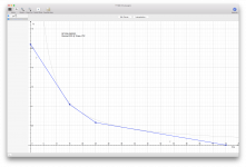
I discovered a little program that I never knew existed, and I used that to plot a derated DC SOA for the 3055 and then plot a 3 slope locus that maybe could be used to design the VI limiter. (attached)
For a while I was thinking a 2 slope might be easier and sufficient, but the 3 slopes makes more use of the available SOA and it's not that much more complex. It doesn't take that many more parts, and those are the cheap type.
So I plotted a potential 3 slope locus, which hugs pretty closely the derated SOA curve. I derated 50C to a case at 75C, which should bring down the power to a little over 82W, so I used 82W for the SOA curve.
I don't know how to properly derate that small part at the low currents and high voltages where there is second breakdown. It's a little bit lower, but how to derate that? Anyone can offer some insight?
The low segment of the locus may have to be moved slightly down to accommodate for the second breakdown..
Attachments
For most types, a specific s/b derating curve is not given. Just a couple of clues like “Second breakdown pulse limits are valid for duty cycles to 10%”, and “at high case temperatures thermal limitations will reduce the power that can be handled...” These statements would imply that you derate thermally first, and if the s/b limit is less, you use that. This is probably ok if the breakpoint between thermal and S/B limits is greater than the rail voltage (half rail to rail). The only reason you will ever sink current below the zero crosssing is driving an inductive load where no current limiting is happening. This out of phase current only happens for a small fraction of a cycle. What really hurts power transistors is just plain trying to drive too much current into a low impedance or short circuit. Running in current limit into a short at bass frequencies ispretty darn near a worst case, and pretty much guaranteed to happen eventually. Dr-rate thermally for that case, and it’s probably pretty safe.
Some transistor types have a thermal derating curve for s/b limits. It is usually linear to 60% of the s/b limit at 200 ( or 150) C case temp. I’ve only seem that curve used with relatively fragile switching types which have very poor s/b SOA anyway.
Some transistor types have a thermal derating curve for s/b limits. It is usually linear to 60% of the s/b limit at 200 ( or 150) C case temp. I’ve only seem that curve used with relatively fragile switching types which have very poor s/b SOA anyway.
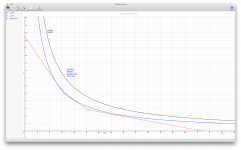
So I guess it's probably fairly safe with that possible locus as on the previous snapshot.
Perhaps to be as safe as possible, making sure not to hug the derated dc curve too closely at the high voltages end would be ok.
I improved that plot a little, so I'm posting it again.
Perhaps to be as safe as possible, making sure not to hug the derated dc curve too closely at the high voltages end would be ok.
I improved that plot a little, so I'm posting it again.
Attachments
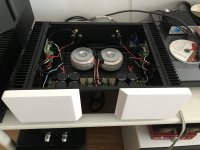

Hiraga "Le monstre" .... TIP3055 TIP2955. A class, easy and sound is good for me!
That's an all different league there. Very nice for the sound, for sure, but we're talking about 20W, or perhaps pump it up so some 30W, with very beefy everything...
We're in a different ballgame here. Trying to do something that's never been done before with 3055s, aiming for well over 200W/8ohms, and more if the bridge is bridged again... More than 10 times what the class A can do.
If someone can make a class A amp with 3055s that can put out more than 200W/8ohms, I'd like to see that! A "tour de force"!!
. Trying to do something that's never been done before with 3055s, aiming for well over 200W/8ohms, and more if the bridge is bridged again... More than 10 times what the class A can do.
So what are you talking about?
- Home
- Amplifiers
- Solid State
- Amplifier based on 2N3055