Well, since it is an n-channel device, the drain must be at a voltage more positive than the source. The source must be at about -125V to put -30V on the grid of the KT88.
So the 50k resistor spans -30V to +450V. The 10k resistor has to span -125V to -30V to pull the grid of the output tube down to the correct negative voltage(-30V). How does one make an n-channel device, which must have the drain at a higher voltage than the source, pull something down? N-channel followers require a pull-down resistor and p-channel followers require a pull-up resistor in order to have something for current to flow through to create an output voltage.
The shunt feedback divider functions as a pull-up, since it is connected to +450 on one side. You have to have something pulling the other side down, so directly substituting an n-channel device won't work because you would have to drive the network with the drain(it must be more positive than the source), which would make it not a follower anymore.
OTOH, you could have a normal n-channel follower with drain connected to a positive voltage with a resistor down to the negative voltage and drive the feedback network with that node. That would add another big power resistor and I think there would be more distortion since my gut tells me that resistor would have to have a lot of current going through it to make this work well. Why not just use a p-channel fet? It is simpler and doesn't create as much heat.
I hope it is clear what the problem is now?
I understand what you're saying and that's all valid.
Let's turn it upside down a bit. The negative swing isn't particularly important once the tube is cut off. All you need is some clamping to protect the n-FET (which I think you need regardless of polarity). So the source resistor only has to have -50V or so across it. The positive swing is likewise only has to go up to +10 to +15V on the grid (I'd have to calculate the source voltage for that). Source impedance has to be small in comparison to 10k, so the idle current isn't a big issue, either. 10mA is more than enough.
Still, this is a really intriguing idea, irrespective of some of these implementation details.
You could put the P-Fet in place of the CCS on the driver plate. (use a source resistor to B+ to degenerate/linearize the V to I, drain connects to the driver tube plate) Then use a resistive divider from the output tube plate to the P-Fet gate to control its current. Plate of the driver then gets C coupled to the output tube grid. So now you have voltage derived current feedback. The residual current then drives the output stage grid resistor. PSRR is now greatly improved over the usual Schade/shunt Fdbk, since the Fdbk is referenced to B+ just like the output on the OT. Current coupling from the Fet to the driver plate isolates the power supply noise then. Impedance at the driver plate can be kept high to maximize local Fdbk loop gain, which will be high here.
This idea has been proposed before by the way. I think Wavebourn had one version like this.
OOPs, that gives positive Fdbk. I think Wavebourn put the feedback R to the Source of the Fet/CCS to fix that. (forming a divider with the Source degeneration resistor to B+) Same idea (gate gets a constant bias V).
Last edited:
Smoking-amp, I stole this idea from one of Michael Koster's drawings ages ago. I just dawned on me that I could just make an output stage like that. In all probability you were involved in whatever thread I got this idea from.
SY,
I guess I don't understand the drive to get rid of the p-channel devices. Will switching to n-channel devices improve performance in any way?
I guess I don't understand the drive to get rid of the p-channel devices. Will switching to n-channel devices improve performance in any way?
Will switching to n-channel devices improve performance in any way?
Possibly: I don't have any data on gm at these (relatively) low currents, but because n-channel have higher carrier mobility, I'd predict significantly lower for p-channel. You have me curious...
Looking at Fairchild's
FQP1P50:
Gfs 1.26 S @ .75 Amp
Cin 270 pF
Pdiss 63 Watt
and FQP1N50:
Gfs 1.04 S @ .7 Amp
Cin 115 pF
Pdiss 40 Watt
I would say the 1P50 part has a bigger die to get its bigger Gfs (Gm), Cin and Pdiss.
FQP1P50:
Gfs 1.26 S @ .75 Amp
Cin 270 pF
Pdiss 63 Watt
and FQP1N50:
Gfs 1.04 S @ .7 Amp
Cin 115 pF
Pdiss 40 Watt
I would say the 1P50 part has a bigger die to get its bigger Gfs (Gm), Cin and Pdiss.
I just got this amplifier back from my brother for a repair and so will be taking comprehensive measurements in the near future. My measurement setup is much better now than it was when I originally did this. The repair is complete so here are the first measurements:
Zout @ output tube bias current:
3.6 Ohms @ 50mA
3.3 Ohms @ 60mA
3.1 Ohms @ 70mA
Overall, Zout is probably in the ballpark I would expect. I think Pete Millet's 300B amp was somewhere near this. It is difficult to go much lower than this on an open-loop amp. For comparison, my open-loop Unity-Coupled amp achieves a Zout of 1.1 Ohms at 50mA with about the same supply voltage and a little higher turns ratio in the output transformer.
I also measured the DCRs of the Hammond 1650R output transformers and the primarly was a little less than 100 Ohms and the secondary is 0.20 Ohms (configured for 8 Ohm operation). I am impressed with the low copper losses of the 1650R. If I were doing this amp again I would build it as a cathode follower amp.
I plan on running a series of distortion measurements at various power levels and various output tube bias currents after I install a bias servo board into this amp. Stay tuned.
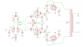
I have updated the amp a bit. Schematic is attached. I modified for a balanced input and changed the feedback ratio from 20% to 30% in the output stage. I also reduced the current in the feedback divider since I don't think 10mA was really necessary. Output stage effective mu is now ~3.3, a little bit lower than a 300V.
Zout @ output tube bias current with new feedback ratio:
2.9 Ohms @ 50mA
2.4 Ohms @ 60mA
2.2 Ohms @ 70mA
Zout @ output tube bias current with new feedback ratio:
2.9 Ohms @ 50mA
2.4 Ohms @ 60mA
2.2 Ohms @ 70mA
Attachments
...a little bit lower than a 300V.
Sorry, I meant 300B in that last post.
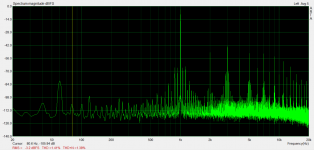
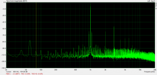
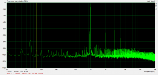
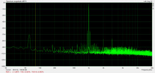
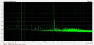
I have attached distortion results of the higher feedback ratio for 100mW, 500mW, 1W, 2W, 5W, 10W, 20W, 40W, and 50W.
Here is a link to a more complete write-up: Tube Amps with a Twist: P-Channel Shunt Feedback KT88 Amp Revisited
Attachments
-
 50W60mA.png143.5 KB · Views: 113
 -
 40W60mA.png140.6 KB · Views: 104
 -
 20W60mA.png131.3 KB · Views: 115
 -
 10W60mA.png129.4 KB · Views: 110
 -
 5W60mA.png128.3 KB · Views: 103
 -
 2W60mA.png126.8 KB · Views: 246
 -
 1W60mA.png122.5 KB · Views: 242
 -
 500mW60mA.png123 KB · Views: 252
 -
 100mW60mA.png119.2 KB · Views: 278
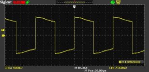
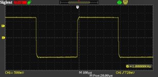
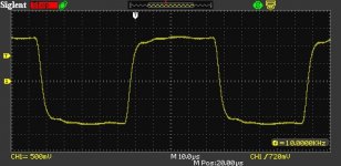
To finish these measurements off, square waves at 20Hz, 1kHz, and 10kHz are attached. Output transformer is a Hammond 1650R.
I think I'm done with this amp.
I think I'm done with this amp.
Attachments
Last edited:
- Status
- Not open for further replies.
- Home
- Amplifiers
- Tubes / Valves
- Amp: KT88 push-pull shunt feedback output via p-channel fet