I think it can be stabilized simply, Paul just likes to try complicated compensation.😉
And I like to try to understand compensation.
My earlier discussion about Damir's similar issues starts >HERE<.
Best wishes
David
Hi David,
This amp can be compensated via shunt compensation alone.
But this would not yield the same performance.
The bootstrapped shunts allow for an extra decade of flat loop gain.
This must come at a price. No free lunch. 😉
Compensation is the key that unlocks potential performance. I believe we are in agreement about this?
Through you following and trying to understand my compensation schemes you help my understanding by offering alternative perspectives. Which has been a big help especially when trying to get an understanding of control loop theory (albeit very basic) 😉
The latest round of observations about my amp's TPMIC tap off point. It seems the prescribers need to be very fast and be able to run at higher bias currents. Running high prescriber bias significantly improves stability into the unrealistic pure 100nF load. The new phase twisting is less pronounced. Do I go for cascoded predriver or similar. Currently the a1381/c3503 pair are being used supplied from the front power rails with no bootstraps and at a bias of 33ma.
Will publish a schematic once I have thouhht some more about the best predriver arrangement.
Paul
P.S. I can't seem to use the shunt in the TPMIC to remove the shunt compensating the vas loop. I think there must be some subtle points that need to be uncovered 🙂
This amp can be compensated via shunt compensation alone.
But this would not yield the same performance.
Best to minimize shunt compensation, nested compensation "wastes" less.
But a little shunt compensation out of the audio band has minimal detrimental effect on distortion and can be effective to improve stability.
This must come at a price. No free lunch. 😉
But we can overpay if we are not careful.
Compensation is the key that unlocks potential performance.
Absolutely.
...control loop theory (albeit very basic)
There is a subtlety that much of the control loop theory is of little relevance to amplifiers.
In fact, despite the vast control theory literature, there is not much that is relevant to the unique problems that constrain amplifiers.
I finally have some results that explain why the control literature is often not applicable and I am surprised that they are not better known.
Does anyone have any references to Nested loop theory?
I can't seem to use the shunt in the TPMIC to remove ... I think there must be some subtle points that need to be uncovered 🙂
I found it effective to lower the impedance of the TPMIC shunt.
But I don't have your extra connections, not sure about the effect of those.
Best wishes
David
Just 10pF shunt compensation tames the circuit(here 22pF).
I have made a housekeeping where I mirror-in the currents for the two long-tail pairs, this also effective controls the VAS current.
Nested compensation is in my view just of an academic nature, performance is already sub-PPM. for better performance in the top of the audio-band a VAS cascode is effective.
Attachments
Last edited:
Just 10pF shunt compensation tames the circuit(here 22pF).
I have made a housekeeping where I mirror-in the currents for the two long-tail pairs, this also effective controls the VAS current.
Nested compensation is in my view just of an academic nature, performance is already sub-PPM. for better performance in the top of the audio-band a VAS cascode is effective.
Hi Miib,
Thank you for your housekeeping ideas. Lots of things to look over the weekend. Thought my evenings were going to empty 😉
I like the idea of moving the Servo outside of the signal path. Also, had considered cascoding the cascode in the VAS but never tried it. The top end ppm is the something that could do with some work. If the top end can be improved then maybe the compensation could be backed off to gain extra stability. Would like to this amplifier to very well behaved with no burst oscillations occurring.
Just been thinking about the LTP mirrors and whether they are necessary to balance the SuperTis style front end. But have to remember they do allow for an alternative Servo connection...
Thank you for all this food for thought. Lots to evaluate 🙂
Paul
The Lunchbreak Amplifier Lives
🙂
A non thermal-trak version to evaluate compensation stability.
In the picture the TP-MIC is disabled but as I type the lunchbreak amplifier is "singing" with all but the lead compensation enabled.
Need to do some more sims and apply in reality.

Now the real fun starts.
Paul
🙂
A non thermal-trak version to evaluate compensation stability.
In the picture the TP-MIC is disabled but as I type the lunchbreak amplifier is "singing" with all but the lead compensation enabled.
Need to do some more sims and apply in reality.
Now the real fun starts.
Paul
Hello all,
After the photo showing a photograph of the prototype PCB, now to give you some more details.
Start off with the basic design:
1) Front end based on Edmond Stewart's SuperTis. This time without current sources and with cascodes. The current sources will be added at at later date but I only have a very limited supply of through-hole JFets. However, have noticed in SMD there is more choice (Something for a future version 😉).
2) Single transistor cascode TIS. Gives the benefits of having a CMCL but without the complexity. This is detailed on Edmond's site:
Super TIS
Have found that with my compensation scheme that the Baxandall version of the TIS brings complexity but without my usable benefit. There was a big gain in loop gain at lower frequencies but nothing at 20kHz. Wonder is my compensation scheme has something to with this?
3) The compensation scheme is still made up from 2 pole bootstrapped shunts on the TIS outputs, TP-MIC, B-C capacitors on the driver transistors and some compensation on the current mirror degeneration.
4) Dropped the Thermal-Trak for the moment and have opted for a plain 3EF with bootstrapped Pre-drivers to minimise the effect of non-linear Cob loading on the TIS.
5) Basic DC servo used so that low values of resistance can be used for the feedback network.
6) Boosted front end power rails.
Think that covers the main features. The circuit posted here is a working circuit. Any suggestions are most welcome 🙂
Some specs from simulations:
THD20K (0.5V off clipping +/- 19.3V): 0.002456%
THD20K ("half power" +/- 9.5V): 0.000103%
THD1K ("half power" +/- 9.5V): 0.000009%
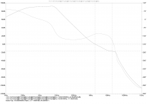
VAS loop stability: PM= 75 degrees GM= 16dB
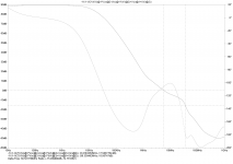
OPS loop stability: PM= 56 degrees GM= 17dB
Attachments:
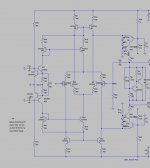
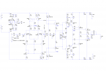
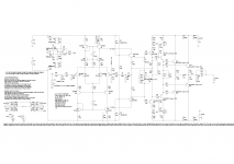
1) Schematic
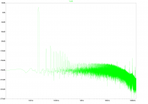
2) 1kHz half power FFT
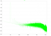
3) 20khz half power FFT
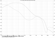
4) OPS Loop Stability Plot
5) VAS Loop Stability Plot
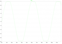
6) Clipping
7) .asc file
Hope this is of some interest to people here. 🙂 The schematic and .asc file is of the working prototype.
Any comments much appreciated. Will be working towards a version 2 PCB with Thermaltrak...
Best wishes,
Paul
After the photo showing a photograph of the prototype PCB, now to give you some more details.
Start off with the basic design:
1) Front end based on Edmond Stewart's SuperTis. This time without current sources and with cascodes. The current sources will be added at at later date but I only have a very limited supply of through-hole JFets. However, have noticed in SMD there is more choice (Something for a future version 😉).
2) Single transistor cascode TIS. Gives the benefits of having a CMCL but without the complexity. This is detailed on Edmond's site:
Super TIS
Have found that with my compensation scheme that the Baxandall version of the TIS brings complexity but without my usable benefit. There was a big gain in loop gain at lower frequencies but nothing at 20kHz. Wonder is my compensation scheme has something to with this?
3) The compensation scheme is still made up from 2 pole bootstrapped shunts on the TIS outputs, TP-MIC, B-C capacitors on the driver transistors and some compensation on the current mirror degeneration.
4) Dropped the Thermal-Trak for the moment and have opted for a plain 3EF with bootstrapped Pre-drivers to minimise the effect of non-linear Cob loading on the TIS.
5) Basic DC servo used so that low values of resistance can be used for the feedback network.
6) Boosted front end power rails.
Think that covers the main features. The circuit posted here is a working circuit. Any suggestions are most welcome 🙂
Some specs from simulations:
THD20K (0.5V off clipping +/- 19.3V): 0.002456%
THD20K ("half power" +/- 9.5V): 0.000103%
THD1K ("half power" +/- 9.5V): 0.000009%
VAS loop stability: PM= 75 degrees GM= 16dB
OPS loop stability: PM= 56 degrees GM= 17dB
Attachments:
1) Schematic
2) 1kHz half power FFT
3) 20khz half power FFT
4) OPS Loop Stability Plot
5) VAS Loop Stability Plot
6) Clipping
7) .asc file
Hope this is of some interest to people here. 🙂 The schematic and .asc file is of the working prototype.
Any comments much appreciated. Will be working towards a version 2 PCB with Thermaltrak...
Best wishes,
Paul
Attachments
I don't like your compensation, not smooth on the phase shift and too close for comfort at 100 KHz, add a little trace inductance to that and you have a potential disaster.
17 pages and no-one feels need to correct that current
of mirror bases is same as current of mirror collectors?
of mirror bases is same as current of mirror collectors?
Time to resurect a 3 year old thread
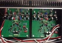
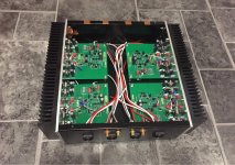
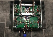
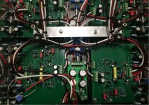
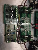
Decided to actually build this one.
Mainly using parts I have accumulated throughout the years.
These pictures of the first dry build.
Lots of work to go.
Have tested 3 of the 4 channels.
Did a quick and dirty test with some passive speakers and the results were certainly promising....
Enjoy 🙂
Paul
Decided to actually build this one.
Mainly using parts I have accumulated throughout the years.
These pictures of the first dry build.
Lots of work to go.
Have tested 3 of the 4 channels.
Did a quick and dirty test with some passive speakers and the results were certainly promising....
Enjoy 🙂
Paul
Attachments


Decided to actually build this one.
Hi Paul
Nice to read the outcome and see the pics, looks tidy.
It's been a while, so detailed comments maybe after I reread to come back up to speed.
Best wishes
David
Hi David,
Bet you had forgotten all about the lunchtime amp 😉
It has been redesigned a little to run off higher voltage rails. +/- 59V for the front end and +/-47V for the output stage. The compensation has been re-tuned as well.
One thing that struck me is how close this compensation is to OITPC (Dadod). I could run an experiment and try OITPC but sims don't suggest any real gain. maybe the folded cascode isn't the ideal VAs to use with OITPC or maybe I am tuning the OITPC incorrectly.
The attached is almost an "as built" schematic. The main difference being the outut devices. The schematic has MJL4281 and MJL4302 whereas I have 2SA1386Y and 2SC3519Y. All front end transistors are matched and the LTP input transistors are a quad match.
Hi Nauta,
The outut devices are currently running at 70mA each.
Attached are the usual plots etc. Current sources are JFET (2sk246).
More pictures will follow...
Paul
Attachments

Last edited:
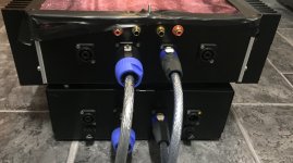
More Progress
Hello all,
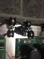
More progress to report. Have now completed the build of a top plate that will sit upside down between the amplifier PCBs. It contains the local output stage decoupling capacitors and a basic SSLR speaker protection system based on bonsai's SSLR PCBs and Rod Elliot's P33 Speaker protection. It has been modified to allow for 4 channels. 2 full range and two midrange / tweeter channels. The Aluminium plate will be remade as it this is the result of designing by "winging" it.
All that is left to do on the amplifier enclosure is to test this circuit, glue heatsinks to the amplifier IPS transistors, connect it all together and test from bench PSUs. Then it is on to completing the PSU...
All the best,
Paul
Hello all,
More progress to report. Have now completed the build of a top plate that will sit upside down between the amplifier PCBs. It contains the local output stage decoupling capacitors and a basic SSLR speaker protection system based on bonsai's SSLR PCBs and Rod Elliot's P33 Speaker protection. It has been modified to allow for 4 channels. 2 full range and two midrange / tweeter channels. The Aluminium plate will be remade as it this is the result of designing by "winging" it.
All that is left to do on the amplifier enclosure is to test this circuit, glue heatsinks to the amplifier IPS transistors, connect it all together and test from bench PSUs. Then it is on to completing the PSU...
All the best,
Paul
Attachments

How is this amp coming along?
Had it working? Listening tests?
People really want to know...... for their lunch break.......
Hugh
Had it working? Listening tests?
People really want to know...... for their lunch break.......
Hugh
What stabilizes the bias current for Q9 and Q10? At a first glance to me it looks unconstrained.
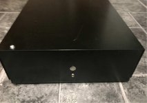
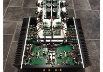
After 2 years you finally got the time to do it 🙂Hello All,
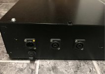
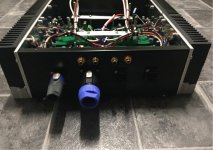
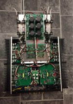
Just another pic of the build. Actually getting somewhere now 🙂
Hopefully finish the amp box today. Then on too finishing the PSU box and the interconnects.
Paul
I still have your pcb's untouched.Now i have one more reason to start doing something with them.
I wonder what happened with the No active load project.For that i really was hoping to see it as a commercial product.The idea was brilliant.
Last edited:
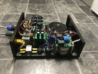
Hi Hugh,
Thank you for your interest in this project. It's almost finished. It has been playing for a while now. Having a few issues with grounding. Slowly but surely the mains hum is disappearing. learning a lot.
As for the sound, it blows my Leach amps out of the water. This amp has a nice crisp high end and a good low end. Better than the Leach amps. The end result is that the mid range is less prominent but much more natural. Sound stage is good. Listening to a Slip knot Live drum solo is fun. You can pick the positions of each drum and cymbal.
The system is an active 2 way main speakers setup with LR4 1.5Khz x-overs with baffle step correction. This is augmented by two sealed subs with Linkwitz transforms. The crossover is another upgrade that came soon after the amp started playing. It is an old project that I never finished. Pictures soon when I next work on it.
Hi Mark,
This front end a variant of Edmund Stuarts Supertis. The connection of the LTPs to the current mirrors along with the folded cascode VAS form a Common Mode Control Loop. Just think in terms of currents and it makes sense. The VAS current is balanced and defined.
Hi Dreamth,
Long time no speak 🙂 If you decide to build this let me know. There are a few tweaks I would do. The active load project had been forgotten about until you mentioned it. I may return to it but right now I'm upgrading most of my system.
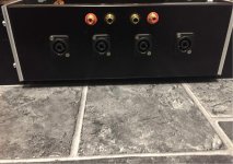
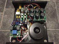
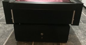
Here are a few pics 🙂 Still to make a proper lid. The cloth is just to prevent stuff from falling in.
Paul
Thank you for your interest in this project. It's almost finished. It has been playing for a while now. Having a few issues with grounding. Slowly but surely the mains hum is disappearing. learning a lot.
As for the sound, it blows my Leach amps out of the water. This amp has a nice crisp high end and a good low end. Better than the Leach amps. The end result is that the mid range is less prominent but much more natural. Sound stage is good. Listening to a Slip knot Live drum solo is fun. You can pick the positions of each drum and cymbal.
The system is an active 2 way main speakers setup with LR4 1.5Khz x-overs with baffle step correction. This is augmented by two sealed subs with Linkwitz transforms. The crossover is another upgrade that came soon after the amp started playing. It is an old project that I never finished. Pictures soon when I next work on it.
Hi Mark,
This front end a variant of Edmund Stuarts Supertis. The connection of the LTPs to the current mirrors along with the folded cascode VAS form a Common Mode Control Loop. Just think in terms of currents and it makes sense. The VAS current is balanced and defined.
Hi Dreamth,
Long time no speak 🙂 If you decide to build this let me know. There are a few tweaks I would do. The active load project had been forgotten about until you mentioned it. I may return to it but right now I'm upgrading most of my system.
Here are a few pics 🙂 Still to make a proper lid. The cloth is just to prevent stuff from falling in.
Paul
Attachments
- Status
- Not open for further replies.
- Home
- Amplifiers
- Solid State
- Amp designed during lunch breaks