I still haven’t eecided if I am going to jig it, use pin sockets or Chokys pot solution. It will dawn on me.
So I have ordered a full kit from the diystore plus a Galaxy case from HiFi2000. Case is a bit deeper than the board so I will need panel mounted RCA sockets and a DC socket instead of the supplied board mounted ones. I will mount the board to the case with metal stand offs but am not sure if I need insulated RCA sockets??
The PCB seems to have the RCA ground be the PCB ground, which would be connected to chassis anyways with the standoffs. So probably no use in extra insulation?
But I would be interested in other’s opinions about this as well. Thanks.
But I would be interested in other’s opinions about this as well. Thanks.
Thanks, how about a dc socket on the rear panel as these don't normally come insuated?Keep routes to chassis ground under control. Insulate.
In my ACP+-build I used insulated RCAs. Also the pcb is insulated (plastic standoffs). I only made 1 connection to ground. As more contact points from audio-ground to chassis ground - as more possibilities for groundloops and noise/hum - my opinion. 🙄
Cheers
Dirk
Cheers
Dirk

As I don't have the kit yet and am only looking at store photos I assume that on the front panel of a case the volume pot and selector switch would naturally contact the metal case as well?In my ACP+-build I used insulated RCAs. Also the pcb is insulated (plastic standoffs). I only made 1 connection to ground. As more contact points from audio-ground to chassis ground - as more possibilities for groundloops and noise/hum - my opinion.
As I don't have the kit yet and am only looking at store photos I assume that on the front panel of a case the volume pot and selector switch would naturally contact the metal case as well?
Both the switch and the VC are electrically insulated from contact to the case by their construction.
The Volume Control is grounded to the RCA inputs through the PCB, you MUST insulate them from contact with the case to avoid a ground loop. Most any chassis mount female RCAs will come with insulators with ridges to fit inside 3/8" holes and do the job. These https://www.amazon.com/Socket-Terminal-Connector-Female-Chassis/dp/B08R3YYCY9/ref=sr_1_5?crid=37ZO84IHGXRRE&dchild=1&keywords=rca+connector+female+panel+mount&qid=1623050353&sprefix=female+rca+connectors+panel%2Caps%2C200&sr=8-5 look like a good choice at a low price. Best would be Vampire CM-Hex from http://www.percyaudio.com/Catalog.pdf Michael Percy without getting crazy expensive.
Both the switch and the VC are electrically insulated from contact to the case by their construction.
The Volume Control is grounded to the RCA inputs through the PCB, you MUST insulate them from contact with the case to avoid a ground loop. Most any chassis mount female RCAs will come with insulators with ridges to fit inside 3/8" holes and do the job. These https://www.amazon.com/Socket-Termin...s,200&sr=8-5 look like a good choice at a low price. Best would be Vampire CM-Hex from http://www.percyaudio.com/Catalog.pdf Michael Percy without getting crazy expensive.
Thanks Bill, I think converting from a ground plane board to a metal case got me overthinking it!
The GND of my PCB is connected to the case via the bolts holding it.
The RCA connectors are isolated from the case. I've only tested it with a CD player and a headphone. It is dead silent. Measurements with my scope confirmed this. The bare PCB picked up noise, but the case shields that now.
I did not yet test when also my source or power amp is connected to mains GND though.
Some measurements
I bought 30 J113 jfets from Onsemi at Conrad
With the test setup from post: #1561 Amp Camp Pre+Headphone Amp - ACP+ I did some measurements.
I set it up in a breadboard and I used a 12Volt power source.
Before measuring the resistance required for 10mA I measured the fets in
a tester that looks very similar to this one: https://www.amazon.com/Aideepen-Mega328-Transistor-Capacitance-Battery/dp/B07RFFMY61/
When I insert a fet it shows the legs for G,D and S, and it gives the current for a given Ugs
I put it all in a table together withe the meausred R that yields 10mA.
The results are the following:
Qty.
_
I(mA)
_
U(V)
_
R@10mA
1 ____ 1.2 ____ 0.86____44
2 ____ 1.4 ____ 1.0 ____ 47
2 ____ 1.3 ____ 0.9 ____ 50
6 ____ 1.5 ____ 1.0 ____ 54
2 ____ 1.5 ____ 1.1 ____ 58
7 ____ 1.7 ____ 1.2 ____ 66
4 ____ 1.6 ____ 1.1 ____ 68
2 ____ 1.8 ____ 1.2 ____ 75
1 ____ 1.8 ____ 1.3 ____ 76
3 ____ 1.9 ____ 1.3 ____ 80
I did some checks whether the same combination of Id and Ugs leads to the same R, and it did. I then assumed this is true for every group (row in the table)
I bought 30 J113 jfets from Onsemi at Conrad
With the test setup from post: #1561 Amp Camp Pre+Headphone Amp - ACP+ I did some measurements.
I set it up in a breadboard and I used a 12Volt power source.
Before measuring the resistance required for 10mA I measured the fets in
a tester that looks very similar to this one: https://www.amazon.com/Aideepen-Mega328-Transistor-Capacitance-Battery/dp/B07RFFMY61/
When I insert a fet it shows the legs for G,D and S, and it gives the current for a given Ugs
I put it all in a table together withe the meausred R that yields 10mA.
The results are the following:
1 ____ 1.2 ____ 0.86____44
2 ____ 1.4 ____ 1.0 ____ 47
2 ____ 1.3 ____ 0.9 ____ 50
6 ____ 1.5 ____ 1.0 ____ 54
2 ____ 1.5 ____ 1.1 ____ 58
7 ____ 1.7 ____ 1.2 ____ 66
4 ____ 1.6 ____ 1.1 ____ 68
2 ____ 1.8 ____ 1.2 ____ 75
1 ____ 1.8 ____ 1.3 ____ 76
3 ____ 1.9 ____ 1.3 ____ 80
I did some checks whether the same combination of Id and Ugs leads to the same R, and it did. I then assumed this is true for every group (row in the table)
Last edited:
Hi guys!
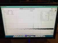
Anyone has a saved distortion spectra of the ACP+ using REW, 1khz internal generator, about 4 to 8 average, no smoothing that you can post? I am trying to figure out if I am doing my set up correctly as I am new to this type of measurement.
Here's a pic of the trial run. Set up is a Macmini to Focusrite Solo, to ACP+, to attenuator, then to Focusrite input. Later on, I will use a battery powered Mac laptop.
Also, how do I create a label on the spectra, as I have seen on other people's graph, before saving it?
Any feedback much appreciated. Thank you!
Attachments
Oops, I forgot to ask, when doing measurement, even in loopback, the DUT needs to drive a load?
Thanks again!
Thanks again!
Here is a good how-to:
Howto - Distortion Measurements with REW
To save, click on the camera symbol in the upper left of the screen. It will open a window for entering a title.
I usually load the DUT. For instance for an amplifier I use an 8 Ohm load. For a preamp I usually use a 10K load (to simulate the input impedance of my amplifiers).
Here is a good how-to:
Howto - Distortion Measurements with REW
To save, click on the camera symbol in the upper left of the screen. It will open a window for entering a title.
I usually load the DUT. For instance for an amplifier I use an 8 Ohm load. For a preamp I usually use a 10K load (to simulate the input impedance of my amplifiers).
Thank you Ben!
Would it be possible to run ACP+ at say, +55v PSU rail (with modifications) and reduced bias current as a preamp in order to drive 50Vpp swing on output into say, 10kohm load?
- Home
- Amplifiers
- Pass Labs
- Amp Camp Pre+Headphone Amp - ACP+