no need to change anything, if you add trimpot to series resistor, except from cosmetic reasons
all numerous happy Campers, having original FW J2, for instance, are listening happy notes, pushed across trimpot , connected in drain of input JFet
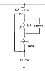
trimpot in CCS, much less critical position
go figure
reminder - how to do
instead of 51, use whatever you have, just recalc voltage sag for 10mA
all numerous happy Campers, having original FW J2, for instance, are listening happy notes, pushed across trimpot , connected in drain of input JFet
trimpot in CCS, much less critical position
go figure
reminder - how to do
instead of 51, use whatever you have, just recalc voltage sag for 10mA
Attachments
You're not measuring resistance. You're measuring voltage across the resistor. That can only be done if the circuit is powered on--either in a test jig, or on the actual PCB.
But yes, after you have the right voltage/resistance combination to equal 10mA you can desolder and measure the resistance so that you can order one resistor of the right value.
I'm no expert but I wonder if leaving the pot in place wouldn't be ok too.
I perhaps expressed myself wrong. Sorry for the confusion.
- I understand I would need to solder the pot or the pot + resistor
- I understand I measure the voltage drop not only in-circuit, but operating
- I move the trim pot to required value
At this point I:
A. NEED to desolder both and measure their resistance off-circuit to determine the correct resistance to purchase, or...
B. COULD measure the resistance of the pot or pot+res in circuit (not turned on) in order to purchase the correct resistance, but keeping the working pot+res in place until they arrive (which will be a month or so)
So, the question is, could I measure the end resistance of the correct values without desoldering to avoid having to resolder those until I get the correct valued resistors?
Thanks agian.
Thanks! Makes perfect sense. So, still I would need to put in R4 something lower than the recommended value, or else I would not be able to overcome the offset, right?no need to change anything, if you add trimpot to series resistor, except from cosmetic reasons...
Hopefully it's all just a thought exercise as mine came out great and sounds magnificent! You shouldn't have to change a thing unless you want to.
Thanks! Makes perfect sense. So, still I would need to put in R4 something lower than the recommended value, or else I would not be able to overcome the offset, right?
it really depends
if you have JFet with higher Idss, you need more than original value of R4
and the other way
no use of babbling, go figure it in vivo

Yeah, still a couple of weeks off of receiving the parts. So I'll stop and ask the questions later! 🙂 Thanks, as always.
Rafa.
Rafa.
I
So, the question is, could I measure the end resistance of the correct values without desoldering to avoid having to resolder those until I get the correct valued resistors?
Thanks agian.
I too need to find out the right values for R4.
You can do that on the PCB, but soldering and desoldering parts can leave a mess on the board. If you have a 12V power supply you can determine R4 with a breadboard. Breadboard - Wikipedia. No soldering required. Another advantage of this method is that you do not accidentally fry other components while experimenting.
So, the question is, could I measure the end resistance of the correct values without desoldering to avoid having to resolder those until I get the correct valued resistors?
I just stuck the resistor in the board, bent the legs just a bit to make sure they made contact, and measured the voltage drop. No soldering necessary until you have found the right resistor value.
I soldered 1-pin sockets in the board and just kept changing resistors until I found the right value. Then I got lazy and soldered it in. Doesn't really change the aesthetic to my eye. When I get motivated enough I'll desolder the pin sockets and solder in the resistors.
OMG! There must be two Audiobears because I have never made a silver cable of any kind. Where did you find the other Audiobear? Hmmmm, this is probably off topic...
I know little about headphones. Are electrostatic headphones a good match for the ACP+? I'm eyeing the Hi-Fi Man Sundaras (37 ohms).
Probably not. When I Google Bear Labs all I get back it hits on a Cannabis products company in California.
Probably not. When I Google Bear Labs all I get back it hits on a Cannabis products company in California.
Ha,ha! No, this one
BEAR Labs CABLES
I might be mistaken. I think the guy was on Audiogon, been fixing amps for ages, if I temember correctly, and also making custom silver cables on order. Last I saw his site he had stopped. But now I can’t find it. Maybe his name was not Audiobear after all. But I think he was from Alaska, and the nick played on that, bears and all
Last edited:
That’s it! Turns out his nick was Bear here on diyaudio.com. Well well, close enough. Thanks, Amanda!
And sorry Audiobear for the mixup 🙂 Though it looks like the hand made silver IC business in his area is up for grabs since 2012.
Cheers,
Andy
hard too is which one makes the music sound better. That said, I am using the ACP+ feeding an M2X-Cedarburg in my main system and really like it. No silver cables or other additives necessary.
- Home
- Amplifiers
- Pass Labs
- Amp Camp Pre+Headphone Amp - ACP+