buy more and select a pair which you'll manage to set at 10mA
or just call any of Boyz around to bring/send you some
🙂
or just call any of Boyz around to bring/send you some
🙂
Hi guys!
Future project will be ACP+. For the planning I have a few questions, and hope you guys can help.
ZM: are you everywhere or just the same places as me?
1: Ideal IDSS of J74s?
2: Toshibas preferred?
3: Where to get J113s, and do I have to match them/use parts with ideal values? Digikey and Mouser seems out.
4: IRFP610. Who sells these?
Regards,
Andy
Last edited:
I'm Omnipresent 
1. slightly less and more than 5mA
2. naah
3. dunno , I wouldn't bother chasing exactly that one - plenty of N Jfets still around; see this if you insist on J113 j113 - Searched phrase | Electronic components. Distributor, online shop – Transfer Multisort Elektronik | Semiconductors | Wide choice of elements and components, electronic parts / TME
4.no one; but plenty of Vendors having IRF510 and IRF610
Yup, like Zardoz!
1: So less than grade B LS. Punky might have some in stock still, so guess that will work out. He’s got cheap ones at 4ma, that OK without circuit mods? Else I’ll just msg them, they prolly got 5ma too.
3: so this thing will work? NTE469 NTE Electronics - Transistor: N-JFET | unipolar; 35V; 2mA; 625mW; TO92; Igt: 50mA | TME - Electronic components If so, chosen at what IDSS?
4: Now I am confused, as always. Is IRF610 and IRFP610 the same part, or is the schem wrong wrt output transistors?
Answering so fast means build break, or are you also omniactive?
Now sleep, redoing my WLS and a lot of family and house stuff. Small brains need sleep too.
Thanks!
Cheers.
Andy
1. damn Vikings - what's wrong with some reading, instead of just typing ?  read this: Beyond the J Fringe
2. where TF is 2?
3.they say it's same part;NTE being Yank side of everything, but let's trust them; you'll need to determine source resistor to get 10mA Iq
4. damn Vikings - what's wrong with some reading, instead of just typing ? there is no IRFP610 ; stare at schematic and pictures some more ...... https://www.firstwatt.com/pdf/art_acp.pdf
Caveat is - it is written IRFP610, but we all know that Papa is allowed to make typos in everything , and Greedy Boyz are in eternal tiptoeing position........ so it's up to you to always stare at schm, Goats and pictures, and deduce what's true, what's deliberate trap
in short - IRFP610 doesn't exist, but IRF610 exist
IRFP series are Biguns, we are putting in amp OS
read this: Beyond the J Fringe2. where TF is 2?
3.they say it's same part;NTE being Yank side of everything, but let's trust them; you'll need to determine source resistor to get 10mA Iq
4. damn Vikings - what's wrong with some reading, instead of just typing ?
there is no IRFP610 ; stare at schematic and pictures some more ...... https://www.firstwatt.com/pdf/art_acp.pdfCaveat is - it is written IRFP610, but we all know that Papa is allowed to make typos in everything , and Greedy Boyz are in eternal tiptoeing position........ so it's up to you to always stare at schm, Goats and pictures, and deduce what's true, what's deliberate trap
in short - IRFP610 doesn't exist, but IRF610 exist
IRFP series are Biguns, we are putting in amp OS
We need an updated R1V2 power supply schematic - it's not the same as shown in Firstwatt ACP+ article.
Here's a clue. When I jumpered between R19 and R20 it bypassed the power switch! Now always on no matter what the position of the switch and the cute blue LED doesn't light.
Here's a clue. When I jumpered between R19 and R20 it bypassed the power switch! Now always on no matter what the position of the switch and the cute blue LED doesn't light.
Tom, Those are great clues. Perhaps your switch is not mounted correctly. Since the switch has a built in LED, perhaps it has a built in voltage dropping resistor to drop the voltage to 5V. .
Maybe if you remount your switch rotated 180 degrees, you will get the switch working properly, but the then LED will not work. If that is the case you can probably attach the third pin of the switch to a point in the power supply to power the LED. Then you can remove the jumper.
That is my guess anyways.
Ben I think you are on to something. I am going to leave it as is for a few days until the new J113's arrive and then explore further.
I did verify that the switching function is between the two red wires. I had wired it in the pin block with black to Ground, one red wire to V+, and the other to the third "dead?" position.
Apparently in the new R1V2 scheme C6-R18-C7-R19 always see the power supply. Switching on sends current to the left channel C8-R20, or right channel C9-R21.
The two functioning switch wires should go to the "live" positions (V+ and Ground) and the non-switch wire should go to the "dead" position. The non-switch wire is probably the power wire for the LED. You can take a wire from a switched power component (R20 or R21) to the non-switch wire to power the LED.
1. damn Vikings - what's wrong with some reading, instead of just typing ?
2. where TF is 2?
3.they say it's same part;NTE being Yank side of everything, but let's trust them; you'll need to determine source resistor to get 10mA Iq
4. damn Vikings - what's wrong with some reading, instead of just typing ?
Caveat is - it is written IRFP610, but we all know that Papa is allowed to make typos in everything , and Greedy Boyz are in eternal tiptoeing position........ so it's up to you to always stare at schm, Goats and pictures, and deduce what's true, what's deliberate trap
in short - IRFP610 doesn't exist, but IRF610 exist
IRFP series are Biguns, we are putting in amp OS
1: Have you ever ever met a Viking that can read? Didn’t think so!
2: Store is out of quad 74’s, so no need for further discussion
3: Happy.
4: Kinda suspected it was a typo, but better to have you say it than me.
Long story short, this is basically down to math. You know me and math. I always need Zardoz for that.
If I get the right value parts I was hoping to follow schematic. But as always you force me into actually thinking during a build. That never ends well.
I’ll do some planning and set up a small matching jig/measuring jig so as to avoid too much unsoldering. I’m quite capable of that. But let’s just say there are more interesting parts to the hobby than unsoldering and replacing stuff. And I know...
.... But let’s just say there are more interesting parts to the hobby than unsoldering and replacing stuff. And I know...
oh, but whenever I'm in situation that brain activity isn't on par with demands, I'm finding repetitive actions veeeery compelling

ACP+ is what the F6 was waiting for!
My ACP+ is not yet at proper operating points but it sounds great!
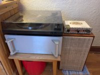
I have been listening to vinyl thru an Ortofon Red, the ACP+, F6, and my Dynaco/Seas A26 speakers. With the ACP+ in the loop the sound unifies, and the F6 which was dry and reserved, finds its voice. The two amps together are almost dead silent, except for snaps and crackles when switching or handling the bare shaft of the Alps. I'm a happy camper.
Now on to replacing the J113's, figuring out the power supply issue, and adapting the case.
Thank you Nelson Pass.
My ACP+ is not yet at proper operating points but it sounds great!
I have been listening to vinyl thru an Ortofon Red, the ACP+, F6, and my Dynaco/Seas A26 speakers. With the ACP+ in the loop the sound unifies, and the F6 which was dry and reserved, finds its voice. The two amps together are almost dead silent, except for snaps and crackles when switching or handling the bare shaft of the Alps. I'm a happy camper.
Now on to replacing the J113's, figuring out the power supply issue, and adapting the case.
Thank you Nelson Pass.
Here's to 6L6 and his generosity
He offered, and I received a set of J113s with accompanying resistors. Can't thank you enough. You saved this paint-by-number builder having to make a test circuit and fool with Ohm's Law. You know, the one that says, "you'll always have the decimal point in the wrong place".
Yesterday, the 4- J113s I ordered before 6L6 made his offer, Newark part #97k2612, arrived from England. Whoever PMs me his address first will receive them in the mail.
I'm finally at the wiring stage of, oddly enough, a 6L6 Amp (although it's getting KT-66s) so the ACP+ is still a few weeks away from start.
An externally hosted image should be here but it was not working when we last tested it.
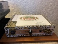
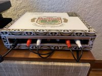
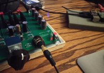
It's Done!
And loaded into it's cigar box case. Some Mozart is playing thru the F6 to the Dynanco/Seas A26 speakers.
I cut the hole for the power switch too low, and the back of switch interfered with board, so some surgery was done. In the process the power switch lost the connection for the pretty blue pilot light.
-Tom-
Attachments
Thank you Ben Mah for your help!
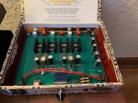
Turns out my assembly was perfect! Until I wired in the power switch! The two red wires go to the power switch, the black wire (now removed) goes to ground just to complete a circuit for the led light.
My other problem was the pair of J113s I got off eBay. They were sad and low energy. One with zero resistance in the circuit only passed about 7mA of current to the left channel. The other got to about 9.6mA with 6 ohm resistance.
I got a roll of 25 J113's to replace them and the first two off the roll matched perfectly! With a 62ohm resistor at R5, I get a voltage drop of 625mV on left and 630mV on right! Bang on specification!
-Tom-
PS: If anybody needs a pair of J113s, PM me.

This is a great headphone amp. I Imagine many more will be built. And as the builder’s pictures show some of those will end up in boxes.
If I may, I have a suggestion. Perhaps on the PCB the switch and LED holes could be moved about 10 mm towards the headphone jack. There is plenty of room. E-Switch makes a ‘right angle’ single pole double throw that matches the the source selector.

It is #100SP1T1B4M7QE and the Mouser page is:
https://www.mouser.com/ProductDetail/E-Switch/100SP1T1B4M7QE?qs=HKd/p3M7KlUx37D2basa8g==
It has the correct action, Up is ON and down is OFF. I used this switch on the current PCB with modifications. I clipped off the locator tangs and milled off most of the top of the machine screw that holds the corner of the PCB. But now the machine screw is forever locked under the switch. And of course I don’t benefit from the locator tangs.
If I may, I have a suggestion. Perhaps on the PCB the switch and LED holes could be moved about 10 mm towards the headphone jack. There is plenty of room. E-Switch makes a ‘right angle’ single pole double throw that matches the the source selector.
It is #100SP1T1B4M7QE and the Mouser page is:
https://www.mouser.com/ProductDetail/E-Switch/100SP1T1B4M7QE?qs=HKd/p3M7KlUx37D2basa8g==
It has the correct action, Up is ON and down is OFF. I used this switch on the current PCB with modifications. I clipped off the locator tangs and milled off most of the top of the machine screw that holds the corner of the PCB. But now the machine screw is forever locked under the switch. And of course I don’t benefit from the locator tangs.
Attachments
- Home
- Amplifiers
- Pass Labs
- Amp Camp Pre+Headphone Amp - ACP+