Hello All,
I am hoping someone can help me understand what is going on with the ACP+ build I just completed last week. Fist off it works and I like it a lot! , With the exception of the grounding issue when touching the volume knob….But here is the part I don’t understand:
I built the ACP using the PDF on the Firstwatt site, so I used the default 125R on R4 will all intention to swap it out. However, when I checked the measurement across R4 I got about .7v on each channel. With the balance so close I decided to see if it would drive some headphones, and to my surprise it did and very well at that. So my issues here is why is this working? I was under the impression that 10ma would be needed for this circuit to operate yet I are half of that. The second part of my question is would there be any downside to just leaving it like this or should I try dropping the resistance value of R4.
An important note I could not source the LSJ74 FETs as they are sold out, so I got impatient and found a matched set of Toshiba J74BL’s with a idss around 10mA.
I am very new to this and don’t have much experience outside of 12V dc systems. Any info would be greatly appreciated.
ignore that it works, because even if it works, it is certainly on the verge of stability
change value of R4 untill you get 10mA though it, observed as voltage sag across, then computed logically (I=U/R)
Help please....
I had a quick check this morning with a laptop supply I have (19V 3.42A) and the LED was solid. Didn't have the time to check the measurements yet, but I think that is a good sign. The capacitor values I have used are all as specified in the BOM. Ordered a new supply and will let you know how things went. Thanks for the replies. Much appreciated.
I had a quick check this morning with a laptop supply I have (19V 3.42A) and the LED was solid. Didn't have the time to check the measurements yet, but I think that is a good sign. The capacitor values I have used are all as specified in the BOM. Ordered a new supply and will let you know how things went. Thanks for the replies. Much appreciated.
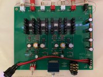
Superb setup. And headphones listening sessions on the rug are always the best
View attachment 943093

It really ties the room together!
Thank you for the advice and comments. I found the correct value for the resistors and now have the 10ma across R4.
I hope there will be a case for the ACP+ similar to the NuTube one in the near future.
I hope there will be a case for the ACP+ similar to the NuTube one in the near future.
It's not working!
My ACP+ build is giving me fits. When I first fired up the amp, I got music on the right channel once I had lowered resistance on R4 to get 6ma current on that channel; since then nothing on either channel (except for 1/2 second on music on the right channel as I was poking about with the multimeter). I have reflowed all the solder joints which caused some of the numbers to be slightly different but still no music.
R4: I got my 2 J113’s from an eBay seller and are claimed to be genuine Fairchild parts. However, I am down to 2.7 Ohm on Left and 3.7 on Right and still have not achieved 10mA. (19.1mV/2.7Ohm = 6.9mA, 33.3mV/3.7Ohm = 9.0mA
I have tried both left and right inputs, I have tried both headphone and line out. The IRF610 Mosfets remain cold to the touch.
Zen Mod suggestions: can you check voltages at important points in circuit?
drain of Q5 (ref to gnd) >> center pin to ground, 5.15V both channels
voltage across any source resistor of output mosfets ?? >>R11, R12, R13 are <1mA
voltage across R4 (ref to gnd) see above
voltage at Q1 gate (ref to gnd) >> L 2.28V, R 2.25V
voltage at both sides of R7 (ref to gnd) >> L 2.25V, 2.21V R 2.15V, 2.11V
Ben Mah suggestions:
1. DC1 to Ground, should be around 11V L 2.92V, R 2.88V
2. across R12, should be about 0.33V L 0, R 0
3. across R4, depends on value of R4, but should not measure 0V see above
4. across R15, should be about 4.5V L 2.36V, R 2.34V
Any suggestions?
The reason I asked for the PS voltage is that you measured 5.15V at Q5 drain, which is connected to the PS voltage (with small drops across R18, R19, R20, and R21). Also 16.5mV across R18, which is 1R, means 16.5mA is being consumed and that is being used by the JFETS. The Mosfets are not conducting.
The question is where is the voltage being dropped? At PS input, there is 24V and at at the start of the amplifier circuit at the Q5 drains (which is also the end of the PS capacitors and resistors), there is 5.15V.
Please take voltage drops across R19, R20, R21, and voltage relative to Ground at between R18/R19 and R19/R20.
Also voltage relative to Ground at the end of R20 and R21 that is closest to the front of the PCB.
Are R18 to R21 1 Ohm as specified?
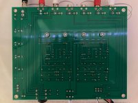
Looking at the picture of the underside of the board, one of the PS input's solder joint looks suspect. Also it probably wouldn't hurt to resolder the joints at the power supply resistors and capacitors.
Another thing, if the current voltage at Q5 drain is 5.15V, that means Q3 is also seeing a low voltage. So the R4 will be too low once the voltage is brought up to specification. Remove R4 until the voltage issue is resolved, then redo R4.
The question is where is the voltage being dropped? At PS input, there is 24V and at at the start of the amplifier circuit at the Q5 drains (which is also the end of the PS capacitors and resistors), there is 5.15V.
Please take voltage drops across R19, R20, R21, and voltage relative to Ground at between R18/R19 and R19/R20.
Also voltage relative to Ground at the end of R20 and R21 that is closest to the front of the PCB.
Are R18 to R21 1 Ohm as specified?
Looking at the picture of the underside of the board, one of the PS input's solder joint looks suspect. Also it probably wouldn't hurt to resolder the joints at the power supply resistors and capacitors.
Another thing, if the current voltage at Q5 drain is 5.15V, that means Q3 is also seeing a low voltage. So the R4 will be too low once the voltage is brought up to specification. Remove R4 until the voltage issue is resolved, then redo R4.
Last edited:
Across R18 16.5mv, R19 16.5mv, R20 5.0mv, R21 9.1mv. From far end to gnd, R18 24v, R19 24v, R20 5mv, R21 5mv. First resistor from tape verified as 1ohm, others not tested.
So something kinky with C8 or R20? Will warm up soldering iron.
So something kinky with C8 or R20? Will warm up soldering iron.
R19 is connected to R20 so different voltage measured with respect to ground? Bad solder joint? Resistance at end of R19 to beginning of R20? Should be no resistance.
Ben, Can resistors be tested in place or must be pulled? What about capacitors? How do I test given a basic multimeter? Thanks, -Tom-
Connected R19 and R20 with a jumper and it plays music and the voltage at the ends of R20 and R21 went to 23.3v. Middle pin of Q6 to Ground is 10v and 9.8v.
What confuses me is that I can see no trace on either the top or bottom of the board connecting R19 and R20! It's the R1V2 board.
I will, again, reflow the PS section and if that doesn't work put a jumper on the bottom of the board.
Thanks for your help Ben, it has been invaluable.
-Tom-
What confuses me is that I can see no trace on either the top or bottom of the board connecting R19 and R20! It's the R1V2 board.
I will, again, reflow the PS section and if that doesn't work put a jumper on the bottom of the board.
Thanks for your help Ben, it has been invaluable.
-Tom-
Last edited:
Should I be concerned that I am using less than 5 ohms on R4 to get the 10ma current? Is this within normal limits for the J113 or should I be looking for another problem?
no
ohms law doesn't lie
if you are having proper voltage sag across resistor, that's it
part you're having is having just slightly higher Idss than 10mA
ohms law doesn't lie
if you are having proper voltage sag across resistor, that's it
part you're having is having just slightly higher Idss than 10mA
Tom,
That is strange that R19 and R20 aren't connected, unless it's just a bad solder joint. But it's great that it's now working.
Also now that you are getting the correct voltage you should recheck the R4 voltage and current.
Ben
That is strange that R19 and R20 aren't connected, unless it's just a bad solder joint. But it's great that it's now working.
Also now that you are getting the correct voltage you should recheck the R4 voltage and current.
Ben
Well left channel is 7.7ma at 1.7ohm, 7.8ma at 0ohm (just the probes)! Right channel is at 9.5ma with 3.9ohm so I will get there with a smaller resistor.
These are the J113's I bought: X2 J113 Transistor, N-Channel FET, 35V 50mA, Switch, TO-92.
-Tom-
These are the J113's I bought: X2 J113 Transistor, N-Channel FET, 35V 50mA, Switch, TO-92.
-Tom-
- Home
- Amplifiers
- Pass Labs
- Amp Camp Pre+Headphone Amp - ACP+