From: https://www.firstwatt.com/pdf/art_acp.pdf
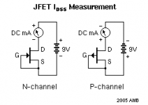
"Q1, Q2 JFETS ARE MATCHED WITHIN 1 MA IDss"
Each JFET operates at 5mA.
The J113 (Q3) CCS controls the overall total current of 10mA.
Sorry I only responded to the reply about Q3. 😉
--Tom
They are waiting for you at the coast.

One day we shall be reunited and listen to Japanese jazz. 🙂
now I see the door where you go to be john malkovich...
I like to be John Malkovich when I listen to music. He has better ears. 🙂
One day we shall be reunited and listen to Japanese jazz. 🙂
my recommendation for that :
?????? ??????BAYCAMP201502???????? - YouTube
🙂
Help a Tube Guy Out?
I'm now in the Q part of the order from Mouser and confronted with:
No J113 except on Ebay where I took a flyer and bought a pair labeled Philips from Taiwan. Bad idea?
Mouser has IRFP up to 4xx but no 610. Other sources, Digikey, Allied, etc., have irf610 no problem. Interchangeable?
I'm now in the Q part of the order from Mouser and confronted with:
No J113 except on Ebay where I took a flyer and bought a pair labeled Philips from Taiwan. Bad idea?
Mouser has IRFP up to 4xx but no 610. Other sources, Digikey, Allied, etc., have irf610 no problem. Interchangeable?
IRFP610 was a typo. I've got IRF610PBF on my order list. I read earlier that J310 will also work in place of the J113. Have not started my build yet so can not confirm if there are any unforeseen problems with that. I have a couple of those I was going to try.
Newark has the J113 https://www.newark.com/on-semiconductor/j113/jfet-transistor-jfet-jfet-35-v/dp/97K2612?st=j113
and the IRF610PBF https://www.newark.com/vishay/irf610pbf/n-channel-mosfet-200v-3-3a-to/dp/27AC6874?st=irf610
Would suggest to buy several J113's and matched a pair for as close value of R4 for L and R. Make it easier to buy resistors later on to try.
You can also use J112 to replace J113 as it is use for CCS.
Attachments
be careful with Newark. I ordered there and received notice that they would be shipped from China and would take weeks (months?) to arrive. Verify arrival time before ordering if you’re in a hurry.
I ordered J113s and IRF610s from Newark last weekend and got them the beginning of this week, fwiw...actually got them faster then my Mouser order since they've been so backed up.
Suddenly I see an LED and R22 not on the B.O.M.
Can't recall any of the zillion posts with a mention. Do I have the ACP (-) ?
It arrived last week.
Anyone have a part number for the LED?
Can't recall any of the zillion posts with a mention. Do I have the ACP (-) ?
It arrived last week.
Anyone have a part number for the LED?
Hello experts!
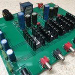
I still have not found the problem with my ACP+. I suspected my DIY speakers to be the problem but figured out when I connect my Dragonfly directly to the ACA monos without ACP+, the harshness is absolutely gone. Already swapped one of the resistors as suggested by one of you but that did not do the trick. Here is a photo, maybe someone can detect a problem. Happy to provide values if needed.
Q1 and Q2 are original Thosiba or LSK fets?
Double check R values!
Please measure voltages across Out-GND, DC1-GND, R4 and R15, R16.
I am not an expert, so I don't have more ideas.
Yeah, for ACP+, I found J310, J113, and J112 will work just fine as ccs. J310 is a 25V device but is well within the max range here. There is one commonality amongst them; however. You still need to find/tune the proper R4 to get 10mA.
R4 for J113 is usually lower than 100R, but >150R for J112 and J310.
R4 for J113 is usually lower than 100R, but >150R for J112 and J310.
IRFP610 was a typo. I've got IRF610PBF on my order list. I read earlier that J310 will also work in place of the J113. Have not started my build yet so can not confirm if there are any unforeseen problems with that. I have a couple of those I was going to try.
Help please....
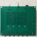
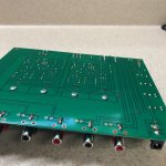
My amp is assembled, but the LED is pulsing constantly. Reading the trouble that Audiobear had I plugged in some older headphones and found that both channels are working fine. The sound pulsates as do measurements I am taking.
My power supply is the recommended class 2 SMPS at 24VDC and 1 amp and I checked the polarity, which was fine. I measured all of the resistors (in place though) and noticed a couple are different values than in the BOM, but I believe as they are in place that can happen. Is that correct? I measured all components before stuffing the board, except I only measured the first resistor if they were on tape. I noticed I that C2 and 3 and different in other builds, whereas mine are the same. C3 is specified as GOLD and C2 not. Is that maybe the issue?
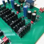
Forgive the big honking screws holding the MOSFETs in place. When I came to fitting the ground plane I saw that they were meant to go there. I tried the amp with and without the plane and it made no difference. The resistor for the LED is 15K, but I read in the forum that's fine.
My amp is assembled, but the LED is pulsing constantly. Reading the trouble that Audiobear had I plugged in some older headphones and found that both channels are working fine. The sound pulsates as do measurements I am taking.
My power supply is the recommended class 2 SMPS at 24VDC and 1 amp and I checked the polarity, which was fine. I measured all of the resistors (in place though) and noticed a couple are different values than in the BOM, but I believe as they are in place that can happen. Is that correct? I measured all components before stuffing the board, except I only measured the first resistor if they were on tape. I noticed I that C2 and 3 and different in other builds, whereas mine are the same. C3 is specified as GOLD and C2 not. Is that maybe the issue?
Forgive the big honking screws holding the MOSFETs in place. When I came to fitting the ground plane I saw that they were meant to go there. I tried the amp with and without the plane and it made no difference. The resistor for the LED is 15K, but I read in the forum that's fine.
Attachments
C3 not being gold is not a problem. The gold C3 is an "audio grade" capacitor but a regular capacitor will work correctly. The difference is a "possible" difference in sound quality, but no difference in electrical function.
The larger LED resistor reduces the brightness of the LED, and will not affect the function of the amplifier.
The pulsing LED, voltages, and amplifier volume sound like something is causing the power supply to malfunction, possibly because more current is being drawn from the power supply than it can provide. You are getting sound so that is a good sign.
One member had that problem because he had installed much more capacitance for C6, C7, C8, and C9. I could only get a glimpse of your capacitors so please confirm that all of your capacitor values are as specified.
Or possibly you have a bad power supply. Please post a picture of the power supply label.
Also please measure some voltages:
1. At power supply input, between V+ and GND
2. Across R20 and R21
3. Both channels across R12 and R4. What is the value of R4?
For the voltage measurements, please try to get the maximum and minimum voltages if the voltages are pulsing.
Since you don't know whether this is a "power supply problem", or an "ACP+ problem", this is where it would be real nice to have something like a lab supply that will definitely absolutely without a doubt work into any load up to a few amps. If it works with a good known PS supply and pulls .3 amps or so and performs perfectly and sounds beautiful.....time to find another SMPS or alternative PS that works.
Hello All,
I am hoping someone can help me understand what is going on with the ACP+ build I just completed last week. Fist off it works and I like it a lot! , With the exception of the grounding issue when touching the volume knob….But here is the part I don’t understand:
I built the ACP using the PDF on the Firstwatt site, so I used the default 125R on R4 will all intention to swap it out. However, when I checked the measurement across R4 I got about .7v on each channel. With the balance so close I decided to see if it would drive some headphones, and to my surprise it did and very well at that. So my issues here is why is this working? I was under the impression that 10ma would be needed for this circuit to operate yet I are half of that. The second part of my question is would there be any downside to just leaving it like this or should I try dropping the resistance value of R4.
An important note I could not source the LSJ74 FETs as they are sold out, so I got impatient and found a matched set of Toshiba J74BL’s with a idss around 10mA.
I am very new to this and don’t have much experience outside of 12V dc systems. Any info would be greatly appreciated.
Last edited:
Working vs. working at the exact (or very nearly) operating condition as intended and specified are different to me. I would adjust my R4 to get that operating current to match the designers intent and resultant sound quality voicing. Only my opinion....
- Home
- Amplifiers
- Pass Labs
- Amp Camp Pre+Headphone Amp - ACP+